4: B
ASIC
I
NSTRUCTIONS
4-22 FC6A S
ERIES
MICROS
MART
L
ADDER
P
ROGRAMMING
M
ANUAL
FC9Y-B1726
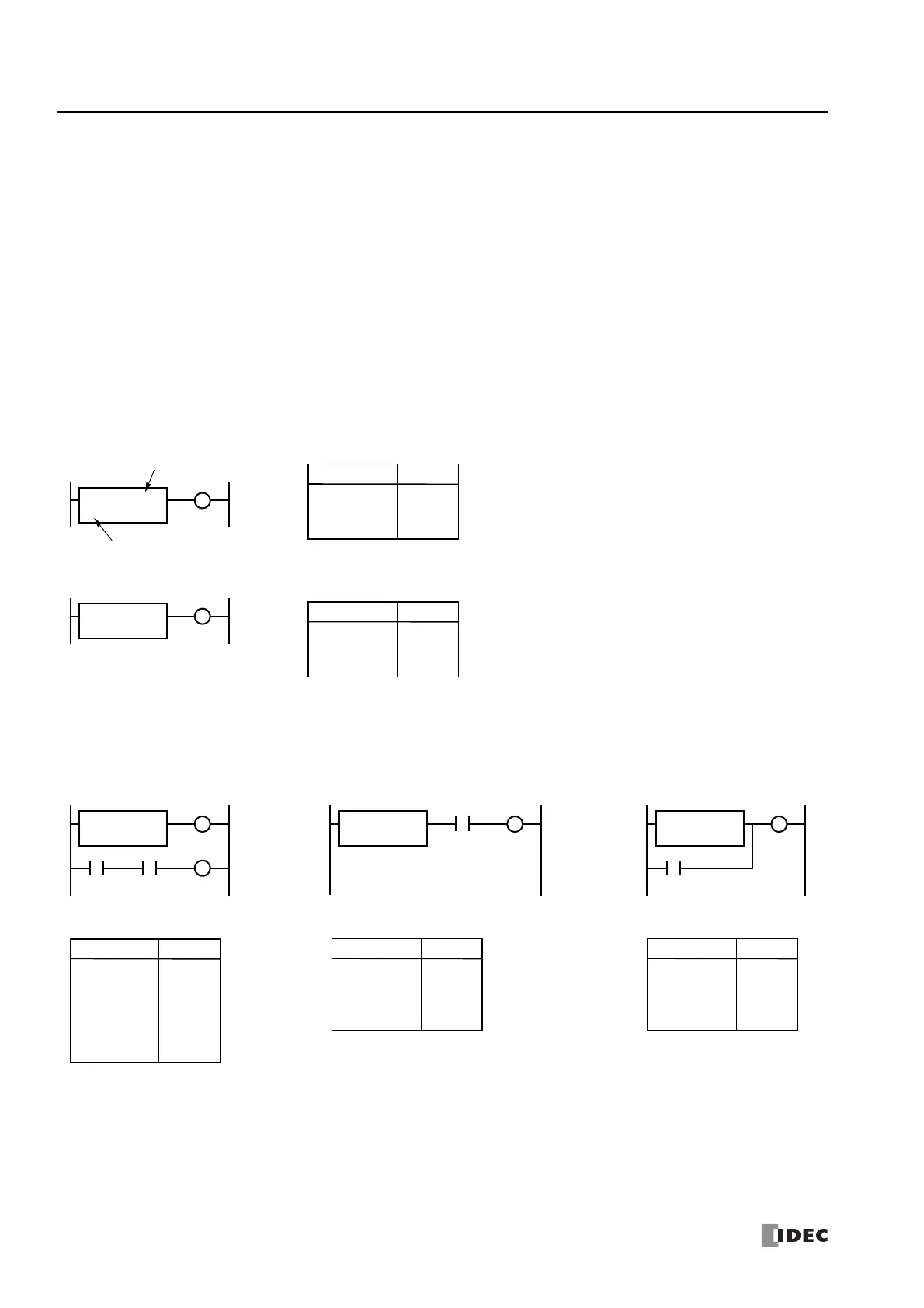
DC= and DC>= (Data Register Comparison)
The DC= instruction is an equivalent comparison instruction for data register values. This instruction will constantly compare data
register values to the value that has been programmed in. When the data register value equals the given value, the desired output
will be initiated.
The DC>= instruction is an equal to or greater than comparison instruction for data register values. This instruction will constantly
compare data register values to the value that has been programmed in. When the data register value is equal to or greater than
the given value, the desired output will be initiated.
When a data register comparison instruction is programmed, two addresses are required. For a constant, specify the value in the
range of 0 to 65,535.
To indirectly specify the value, specify it with a data register number, and specify the value of the data register in the range of 0 to
65,535.
The preset value can be designated using a decimal constant or a data register. When a data register is used, the data of the data
register becomes the preset value.
For LC (Load Compare) instructions, see "LC= (Load Compare Equal To)" on page 6-8.
• The DC= and DC>= instructions can be repeated for different preset values.
• The comparison instructions also serve as an implicit LOD instruction.
• The comparison instructions can be used with internal relays, which are ANDed or ORed at a separate program address.
• Like the LOD instruction, the comparison instructions can be followed by the AND and OR instructions.
Ladder Diagram (DC=)
Ladder Diagram (DC>=)
Data register # to compare with
Preset value to compare
DC=
50
D2
DC>=
D15
D3
Q0
Q1
DC=
OUT
D2
50
Q0
Instruction Data
DC>=
OUT
D3
D15
Q1
Instruction Data
Program List
Program List
Ladder Diagram Ladder Diagram Ladder Diagram
I0I0 M0
DC=
10
D5 DC=
10
D5
I0
DC=
10
D5
M0
Q0
Q0 Q0
DC=
AND
OUT
D5
10
I0
Q0
Program List
Instruction Data
DC=
OUT
LOD
AND
OUT
D5
10
M0
I0
M0
Q0
Program List
Instruction Data
DC=
OR
OUT
D5
10
I0
Q0
Program List
Instruction Data

 Loading...