12: D
ISPLAY
I
NSTRUCTIONS
12-20 FC6A S
ERIES
MICROS
MART
L
ADDER
P
ROGRAMMING
M
ANUAL
FC9Y-B1726
DISP (Display)
Note: Always use transistor output to display data using the DISP instruction.
Valid Devices
For the valid device address range, see "Device Addresses" on page 2-1.
*1 When T (timer) or C (counter) is used as S1, the timer/counter current value (TC or CC) is read out.
*2 Special internal relays cannot be designated as Q.
Conversion
BCD:To connect BCD (decimal) display units
BIN:To connect BIN (hexadecimal) display units
Latch Phase
*1
and Data Phase
*1
Select the latch and data phases to match the phases of the display units in consideration of sink or source output of the output
module.
*1 The LAT (latch phase) and DAT (data phase) settings will differ depending on the 7-segment display sink output specification and source output
specification. Configure these settings according to the specifications of the 7-segment display.
Specify the data to display on the 7-segment display with S1 (the display data). Specify the output for the display data with Q.
Starting from the device specified with Q, the specified data (4 points + number of digits) is sequentially allocated by the display
data and the number of display digits.
For example, if the number of display digits is 4 digits and the display data output is set to Q0, Q0 to Q7 are allocated (Q0 to Q3
are allocated to the data signal to the display, Q4 to Q7 are allocated to the digit selection signal).
Notes:
• A maximum of 8 DISP instructions can be entered in a user program.
• The displayable range is 0 to 65535 (FFFFh).
• Displaying one digit of data requires 3 scan times after the input to the DISP instruction is turned on. Keep the input to the DISP instruction
for the period of time shown below to process all digits of the display data.
Display Processing Time
3 scan times × Quantity of digits
When the scan time is less than 2 ms, the data cannot be displayed correctly. When the scan time is too short to ensure normal display, set a
value of 3 or more (in ms) to data register D8022 (constant scan time preset value).
Displays the specified data on a 7-segment display.
When the input is on, the data specified by S1 is displayed
on the 7-segment display.
Display data can be 0 through 65535 (FFFFh).
Device Function I Q M R T C D P Constant Repeat
S1 (Source 1) Data to display ————X
*1
X
*1
X— — —
Q (Output) Display data output — X X
*2
————— — —
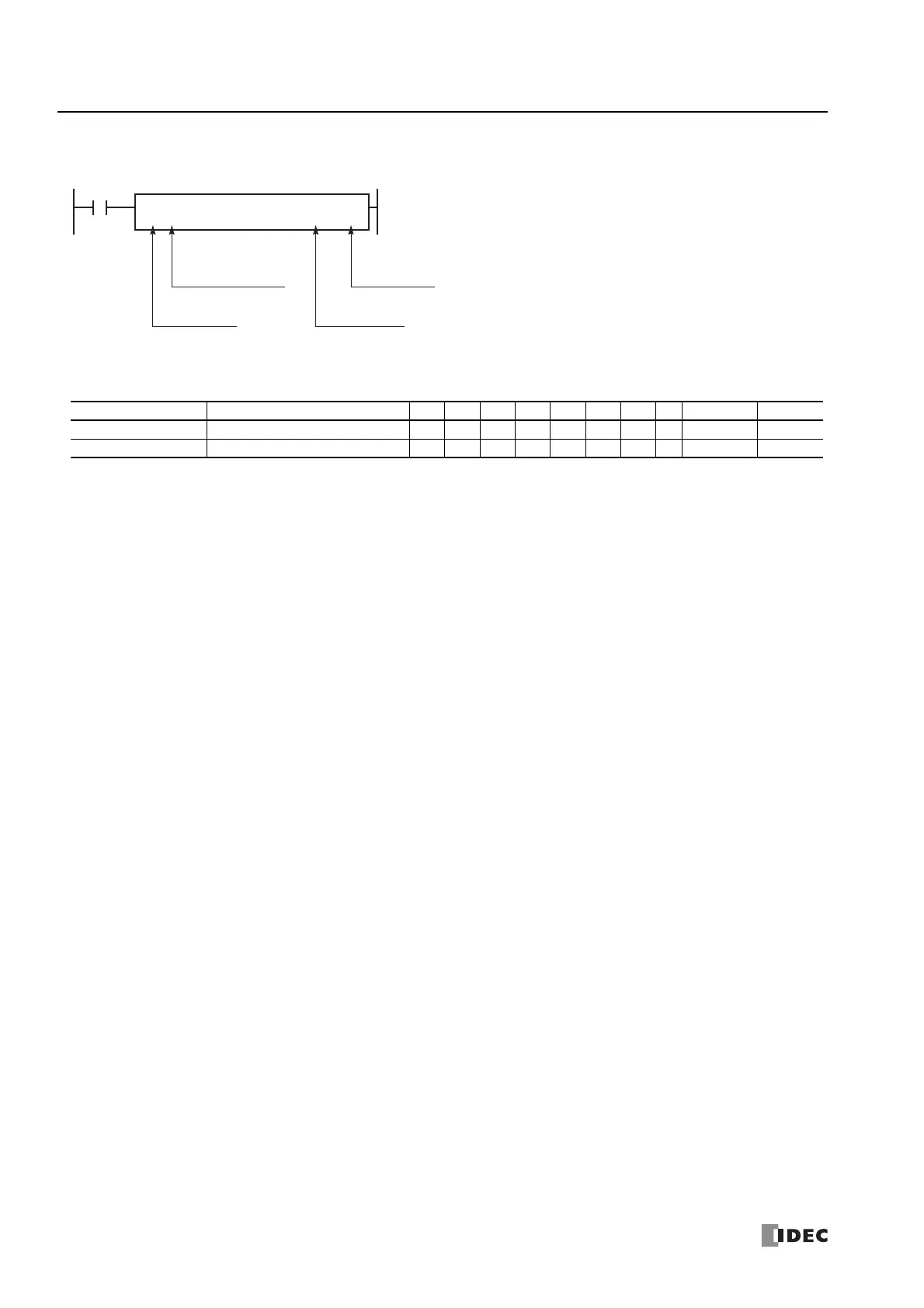
Latch phase:
Low or High
Data phase:
Low or High
Conversion:
BCD or BIN
DISP DATS1
*****
Q
*****
BCD4
LAT
LL
Quantity of digits:
1 to 5 (decimal)
1 to 4 (hex)

 Loading...