9: S
HIFT
/ R
OTATE
I
NSTRUCTIONS
9-10 FC6A S
ERIES
MICROS
MART
L
ADDER
P
ROGRAMMING
M
ANUAL
FC9Y-B1726
ROTR (Rotate Right)
Valid Devices
For valid device address ranges, see "Device Addresses" on page 2-1.
Special internal relays cannot be designated as S1.
The number of bits that can be rotated is 1 through 15 for word data, or 1 through 31 for double-word data.
Since the ROTR instruction is executed in each scan while input is on, a pulse input from a SOTU or SOTD instruction should be used.
Valid Data Types
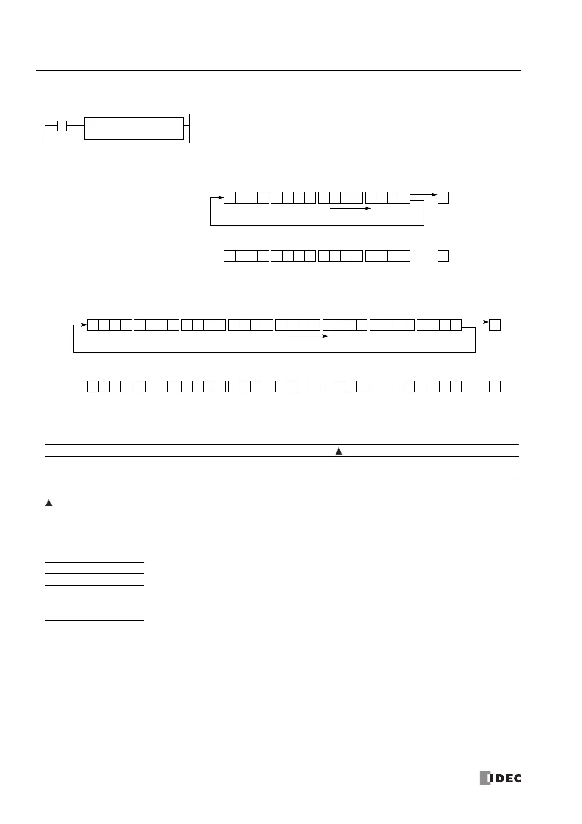
When input is on, 16- or 32-bit data of the assigned source device S1 is rotated to the right by the
quantity of bits assigned by device bits.
The result is set to the source device S1, and the last bit status rotated out is set to special internal
relay M8003 (carry or borrow).
Before rotation: 1 0 1010 1 0 1 1 1101 0 0
CY
M8003
MSB LSB
S1
0After rotation: 1 1100 0 0 1 1 0010 1 1
CY
M8003
MSB LSB
S1
1
Rotate to the right
• Data Type: Word (bits to rotate = 1)
Before rotation:
1 0 1010 1 0 1 1 1101 0 0
CY
M8003
MSB LSB
S1
0
After rotation:
CY
M8003
MSB LSB
S1
Rotate to the right
1 0 1010 1 0 1 1 1101 0 0
• Data Type: Double Word (bits to rotate = 1)
1 1100 0 0 1 1 0010 1 1 1 1 1100 0 0 1 1 0010 1 1 1
Device Function I Q M R T C D P Constant Repeat
S1 (Source 1) Data for bit rotation — X X — — X — — —
bits Quantity of bits to rotate — — — — — — — —
1-15,
1-31
—
W (word) X When a bit device such as Q (output), M (internal relay), or R (shift register) is assigned as the source, 16 points
(word data) or 32 points (double-word data) are used.
When a word device such as D (data register) is assigned as the source, 1 point (word data) or 2 points (double-
word data) are used.
I (integer) —
D (double word) X
L (long) —
F (float) —

 Loading...