FC6A S
ERIES
MICROS
MART
L
ADDER
P
ROGRAMMING
M
ANUAL
FC9Y-B1726 18-1
18: PULSE OUTPUT INSTRUCTIONS
Introduction
This chapter describes the pulse output instructions that output pulses of a specified frequency from the pulse outputs.
PULS (Pulse Output)
Note: Configure multiple PULS (pulse output), PWM (pulse width modulation), RAMP (trapezoidal control), and ARAMP (RAMP with table)
instructions so that they do not share the same output.
However, the ZRN (zero return) instruction can be configured with the same output as the PULS (pulse output), PWM (pulse width modulation),
RAMP (trapezoidal control), and ARAMP (RAMP with table) instructions.
Notes:
• If a pulse output instruction is simultaneously executed with the same output, a user program execution error will occur.
Error code 48 will be stored in D8006 and instructions that are executed later will be canceled.
• The PULS instruction cannot be used in an interrupt program. If used in an interrupt program, a user program execution error will occur.
Error code 18 will be stored in D8006 and instruction execution will be canceled.
• If a pulse output instruction is executed with the relay output type, a user program execution error will occur.
Error code 19 is stored in D8006 and instruction execution is canceled.
• For details about the user program execution errors, see "User Program Execution Errors" on page 3-10.
Valid Devices
*1 Special data registers cannot be used.
*2 Special internal relays cannot be used. Only 0 can be specified as the first digit of the internal relay number. 1 to 7 cannot be specified.
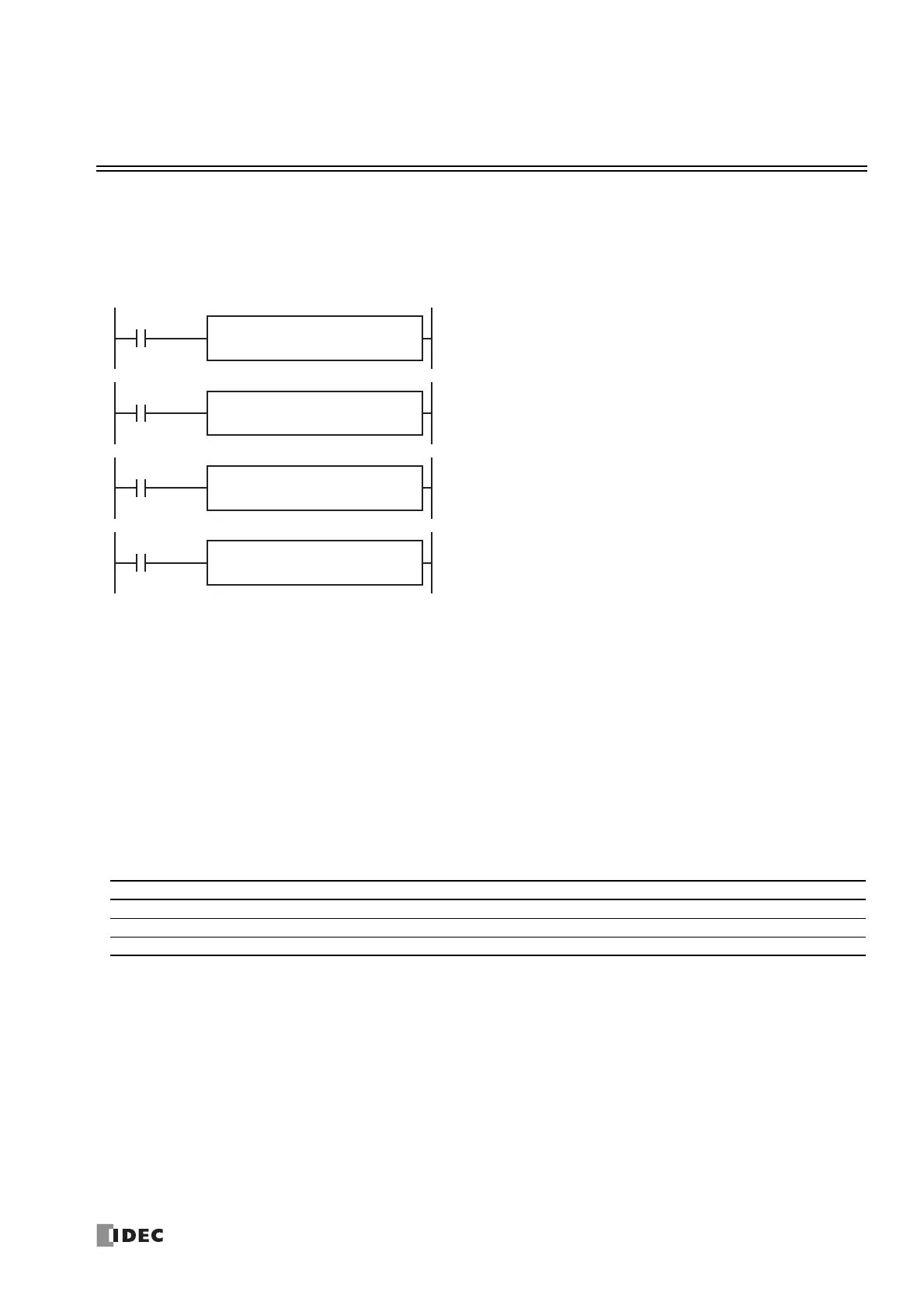
The PULS instruction outputs pulses of the specified frequency from the pulse
outputs with a fixed duty cycle.
When the input is on, pulses are output with a fixed duty cycle according to the
control register settings specified by S1.
When the initialization input specified by S2 is turned on, the initial values
configured in the WindLDR PULS dialog box, on the Settings tab, are stored in
the control registers.
The pulse control information (output on/output complete/error) is stored in the
internal relays specified by D1 as the operation status.
D1
*****
S2
*****
PULS
1
S1
*****
D1
*****
S2
*****
PULS
2
S1
*****
D1
*****
S2
*****
PULS
3
S1
*****
D1
*****
S2
*****
PULS
4
S1
*****
Device Function I Q M R T C D P Constant Repeat
S1 (Source 1) Control register ——————X
*1
—— —
S2 (Source 2) Initialization input X — X — — — — — — —
D1 (Destination 1) Operation status — — X
*2
———— — — —

 Loading...