5: M
OVE
I
NSTRUCTIONS
5-18 FC6A S
ERIES
MICROS
MART
L
ADDER
P
ROGRAMMING
M
ANUAL
FC9Y-B1726
TCCST (Timer/Counter Current Value Store)
Valid Devices
For valid device address ranges, see "Device Addresses" on page 2-1.
When T (timer) or C (counter) is used as S1, the timer/counter current value (TC or CC) is displayed. T (timer) or C (counter) is used as D1, and the
data is written in as a current value (TP or CP).
Since the TCCST instruction is executed in each scan while input is on, a pulse input from a SOTU or SOTD instruction should be used.
Valid Data Types
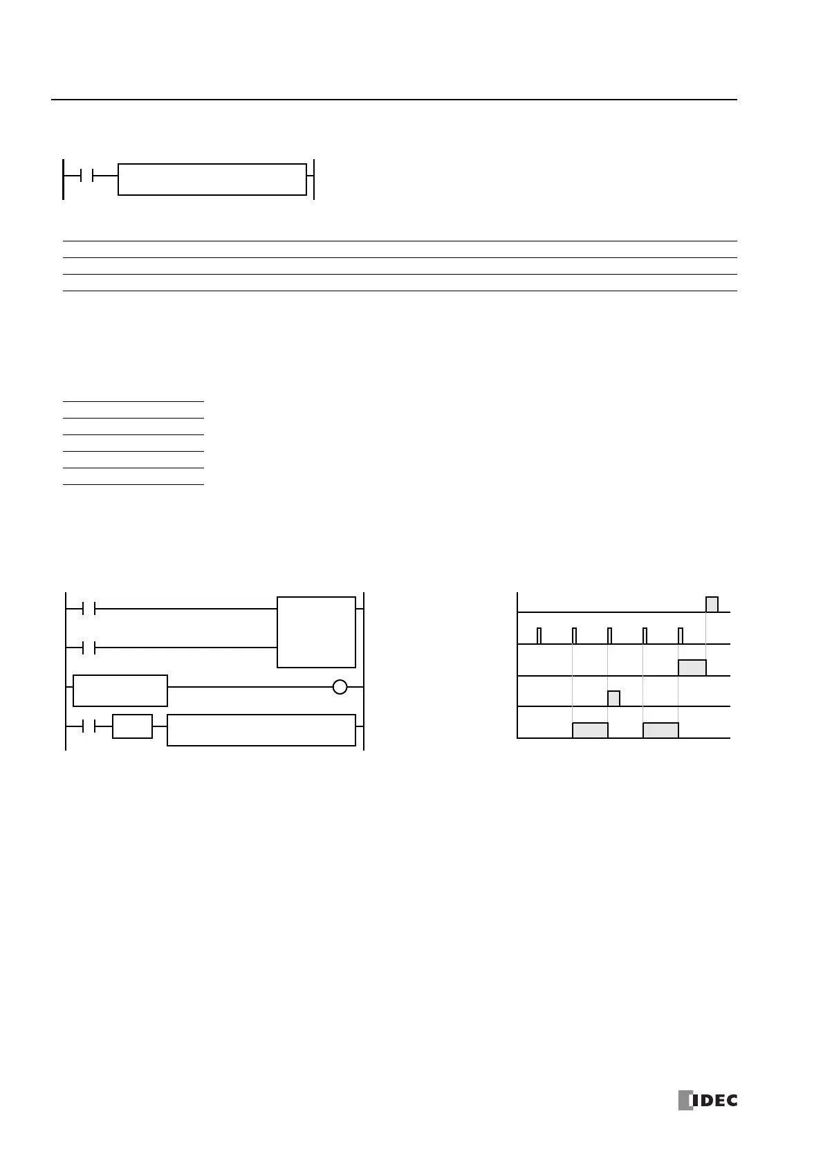
Example: TCCST
When input I2 is turned on, 99,998 is written to the current value of counter C23.
S1 → D1
When input is on, 16- or 32-bit data assigned by S1 is displayed and stored to the
current value of device assigned by D1.
REP
**
S1(R)
*****
D1(R)
*****
TCCST(*)
Device Function I Q M R T C D P Constant Repeat
S1 (Source 1) First device address to move XXXXXXX— X 1-99
D1 (Destination 1) First device address to move to — — — — X X — — — 1-99
W (word) X When a bit device such as I (input), Q (output), M (internal relay), or R (shift register) is assigned as the source,
16 points (word data) or 32 points (double-word data) are used. When repeat is assigned for a bit device, the
quantity of device bits increases in 16- or 32-point increments.
When a word device such as T (timer), C (counter), or D (data register) is assigned as the source or destination,
1 point (word data) or 2 points (double-word data) are used. When repeat is assigned for a word device, the
quantity of device words increases in 1- or 2-point increments.
I (integer) —
D (double word) X
L (long) —
F (float) —
I2
REP
S1 –
99998
D1 –
C23
TCCST(D)
CNTD C23
100000
I1
I0
Q0
SOTU
LC=(D)
C23 99999
Reset Input I0
ON
OFF
Pulse Input I1
ON
OFF
Counter C23
ON
OFF
Timing Chart
Output Q0
ON
OFF
99998
Input I2
99999 99998
ON
OFF
Ladder Diagram
99999
100000

 Loading...