FC6A S
ERIES
MICROS
MART
L
ADDER
P
ROGRAMMING
M
ANUAL
FC9Y-B1726 16-3
16: C
OORDINATE
C
ONVERSION
I
NSTRUCTIONS
CVYTX (Convert Y to X)
Valid Devices
For valid device address ranges, see "Device Addresses" on page 2-1.
Special internal relays cannot be designated as D1.
When T (timer) or C (counter) is used as S2, the timer/counter current value (TC or CC) is displayed. When T (timer) or C (counter) is used as D1,
the data is written in as a preset value (TP or CP) which can be 0 through 65,535.
S1 (Format number)
Select a format number 0 through 7 which have been set using the XYFS instruction. When an XYFS instruction with the corresponding format
number is not programmed, or when XYFS and CVYTX instructions of the same format number have different data type designations, a user
program execution error will result, turning on special internal relay M8004 and the ERR LED on the FC6A Series MICROSmart. For details about the
user program execution errors, see "User Program Execution Errors" on page 3-10.
S2 (Y value)
Enter a value for the Y coordinate to convert, within the range specified in the XYFS instruction. Two different data ranges are available depending
on the data type.
D1 (Destination to store results)
The conversion result of the X value is stored to the destination.
Valid Data Types
Data Conversion Error
The data conversion error is ±0.5.
Note: The CVYTX instruction cannot be used in an interrupt program.
If used, a user program execution error will result, turning on special internal relay M8004 and the ERR LED on the FC6A Series MICROSmart. For
details about the user program execution errors, see "User Program Execution Errors" on page 3-10.
When input is on, the Y value assigned by device S2 is converted into the
corresponding X value according to the linear relationship defined in the XYFS
instruction. Device S1 selects a format from a maximum of 8 XY conversion formats.
The conversion result is set to the device assigned by D1.
CVYTX(*) S1
*
S2
*****
D1
*****
Device Function I Q M R T C D P Constant Repeat
S1 (Source 1) Format number ———————— 0 to 7 —
S2 (Source 2) Y value XXXXXXX—
0 to 65,535
–32,768 to 32,767
—
D1 (Destination 1) Destination to store results — X X X X X — — —
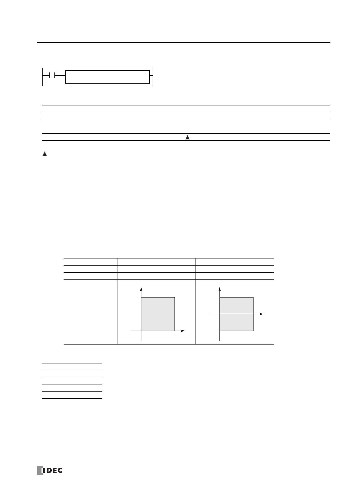
Data Type Word Integer
S2 (Y value) 0 to 65,535 –32,768 to 32,767
D1 (X value) 0 to 65,535 0 to 65,535
Valid Coordinates
W (word) X When a bit device such as I (input), Q (output), M (internal relay), or R (shift register) is assigned as S2 or D1, 16
points are used.
When a word device such as T (timer), C (counter), or D (data register) is assigned as S2 or D1, 1 point (integer
data) is used.
I (integer) X
D (double word) —
L (long) —
F (float) —

 Loading...