FC6A S
ERIES
MICROS
MART
L
ADDER
P
ROGRAMMING
M
ANUAL
FC9Y-B1726 22-3
22: L
OGARITHM
/ P
OWER
I
NSTRUCTIONS
EXP (Exponent)
Valid Devices
For valid device address ranges, see "Device Addresses" on page 2-1.
When the operation result is not within the range between –3.402823 × 10
38
and –1.175495 × 10
–38
or between 1.175495 × 10
–38
and
3.402823 × 10
38
, special internal relay M8003 (carry or borrow) is turned on except when the result is 0. For details, see "Carry and Borrow in
Floating-Point Data Processing" on page 3-8.
When the operation result is between –1.175495 × 10
–38
and 1.175495 × 10
–38
, the destination device designated by D1 stores 0. When the
operation result is less than –3.402823 × 10
38
or larger than 3.402823 × 10
38
, causing an overflow, the destination device designated by D1 stores a
value of minus or plus infinity.
When the data designated by source device S1 does not comply with the normal floating-point format, a user program execution error occurs, and
the execution of the instruction is canceled. The value of D1 is left unchanged and the next instruction is executed.
When a user program execution error occurs, special internal relay M8004 and ERR LED on the FC6A Series MICROSmart are turned on. For details
about the user program execution errors, see "User Program Execution Errors" on page 3-10.
Since the EXP instruction is executed in each scan while input is on, a pulse input from a SOTU or SOTD instruction should be used.
Valid Data Types
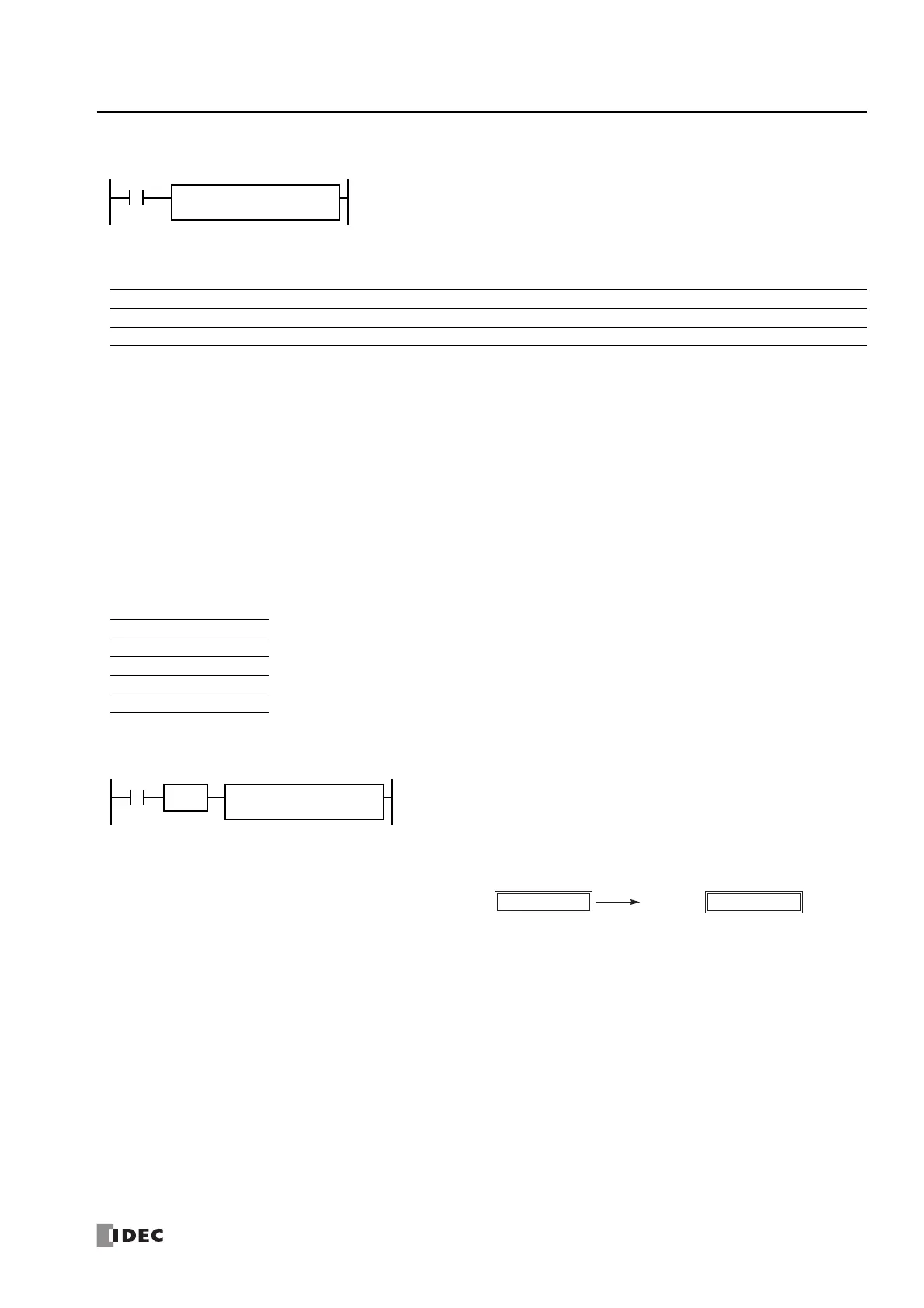
Example: EXP
e
S1·S1+1
→ D1·D1+1
When input is on, e is raised to the power S1·S1+1 assigned by source device S1 and is stored to
the destination assigned by device D1.
e (base of natural logarithm) = 2.7182818
Device Function I Q M R T C D P Constant Repeat
S1 (Source 1) Binary data of exponent ——————X — X —
D1 (Destination 1) Destination to store results — — — — — — X — — —
W (word) — Since floating point data is used, the source and destination devices use two consecutive data registers.
I (integer) —
D (double word) —
L (long) —
F (float) X
When input I1 is on, e is raised to the data of data registers D10 and D11 assigned by
source device S1 and the operation result is stored to data registers D20 and D21
assigned by destination device D1.
e
2
= 2.7182818
2
→ 7.389056
D1S1
2.0
D10·D11
7.389056
D20·D21

 Loading...