FC6A S
ERIES
MICROS
MART
L
ADDER
P
ROGRAMMING
M
ANUAL
FC9Y-B1726 24-9
24: C
LOCK
I
NSTRUCTIONS
HTOS (HMS to Sec)
Valid Devices
For valid device address ranges, see "Device Addresses" on page 2-1.
Source device S1 occupies 3 consecutive data registers starting with the designated device.
Destination device D1 occupies 2 consecutive data registers to store double-word data, starting with the designated device.
Hour data can be 0 through 65,535. Minute and second data can be 0 through 59.
When any of the hour, minute, or second data exceeds the valid range, a user program execution error will result, turning on special internal relay
M8004 and the ERR LED on the FC6A Series MICROSmart. When a user program execution error occurs, the execution of the instruction is canceled
and the next instruction is executed.
When the execution of the instruction is canceled, the data in D1 and D1+1 is left unchanged. For details about the user program execution errors,
see "User Program Execution Errors" on page 3-10.
Since the HTOS instruction is executed in each scan while input is on, a pulse input from a SOTU or SOTD instruction should be used.
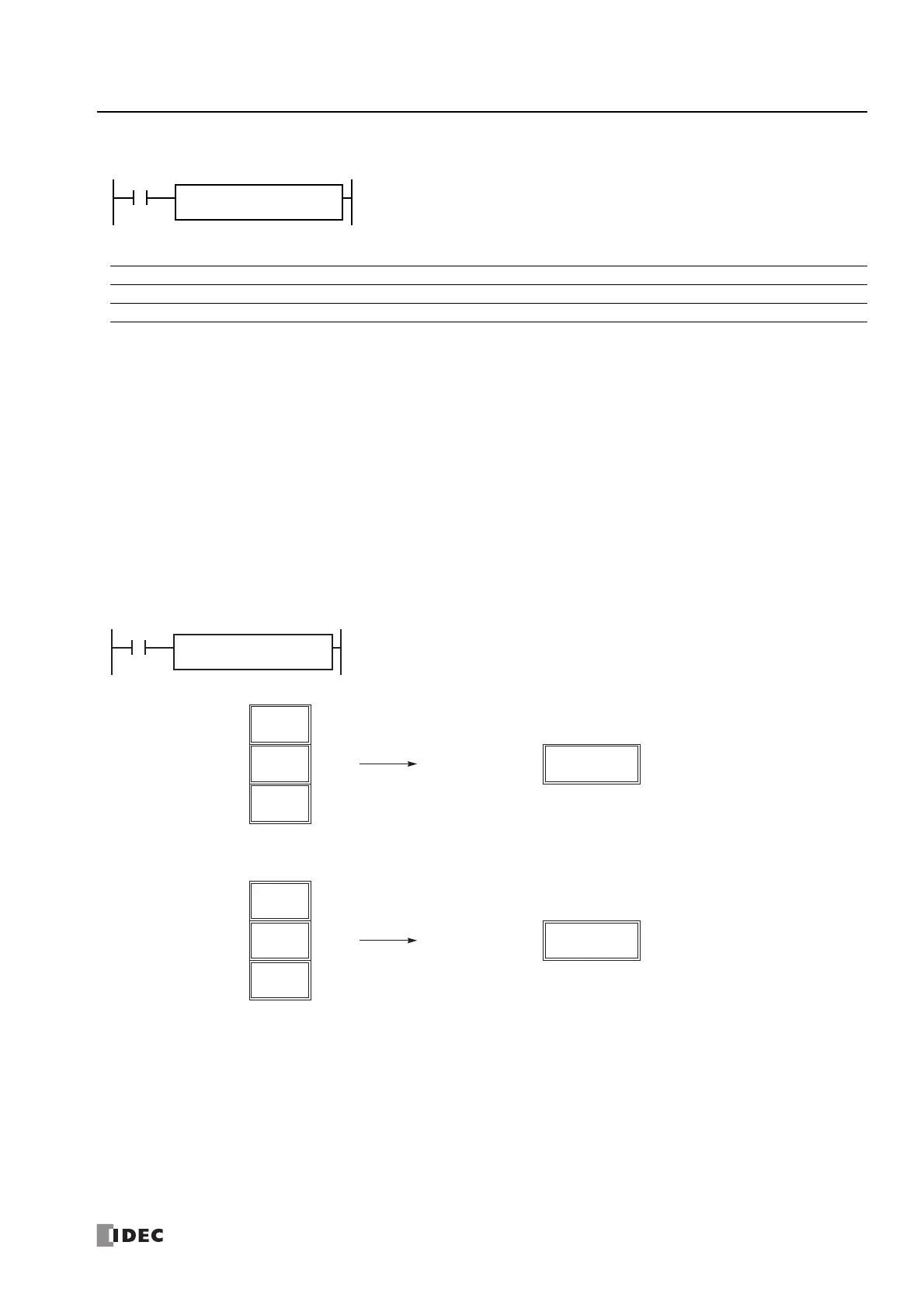
Examples: HTOS
The following examples demonstrate the HTOS instruction that will convert time data in hours, minutes, and seconds into seconds
and store the results to two consecutive data registers.
Hours, minutes, seconds → Seconds
When input is on, time data in hours, minutes, and seconds assigned by source device S1 is
converted into seconds. The result is stored to destination device D1.
Device Function I Q M R T C D P Constant Repeat
S1 (Source 1) Time data in hours, minutes, seconds — — — — — — X — — —
D1 (Destination 1) Destination to store results — — — — — — X — — —
7840
D100·D101
(Second)
Destination 1
I0
D1
D100
S1
D0
HTOS
Source 1
2
D0
(Hour)
10
D1
(Minute)
40
D2
(Second)
Source 1
40
D0
(Hour)
30
D1
(Minute)
20
D2
(Second)
145820
D100·D101
(Second)
Destination 1

 Loading...