FC6A S
ERIES
MICROS
MART
L
ADDER
P
ROGRAMMING
M
ANUAL
FC9Y-B1726 4-1
4: BASIC INSTRUCTIONS
Introduction
This chapter describes the basic instructions that perform sequence control.
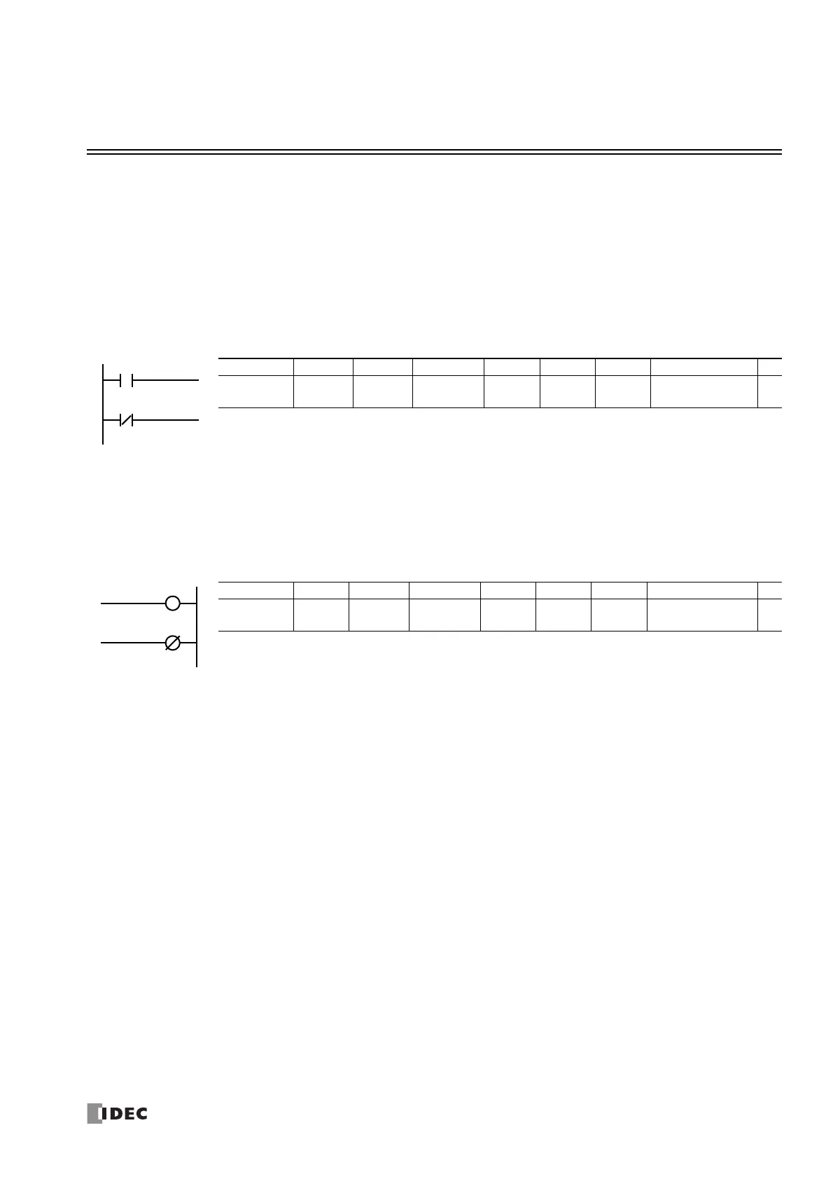
LOD (Load) and LODN (Load Not)
The LOD instruction starts the logical operation with a NO (normally open) contact. The LODN instruction starts the logical
operation with a NC (normally closed) contact.
A total of eight LOD and/or LODN instructions can be programmed consecutively.
OUT (Output) and OUTN (Output Not)
The OUT instruction outputs the result of bit logical operation to the specified device. The OUTN instruction outputs the inverted
result of bit logical operation to the specified device.
Note: For restrictions on ladder programming of OUT and OUTN instructions, see "Restriction on Ladder Programming" on page 4-33.
Valid Devices
Instruction I Q M T C R D P
LOD
LODN
0-27
30-10597
0-17
30-10597
0-7997
10000-21247
0-1999 0-511 0-225
0.0-7999.15
10000.15-61999.15
—
The valid device range depends on the FC6A Series MICROSmart type. For details, see "Device Addresses" on page
2-1.
Specify the bit by inserting a "." between the data register number and the bit position.
Valid Devices
Instruction I Q M T C R D P
OUT
OUTN
—
0-17
30-10597
0-7997
10000-21247
———
0.0-7999.15
10000.15-61999.15
—
The valid device range depends on the FC6A Series MICROSmart type. For details, see "Device Addresses" on page
2-1.
Specify the bit by inserting a "." between the data register number and the bit position.

 Loading...