4: B
ASIC
I
NSTRUCTIONS
4-16 FC6A S
ERIES
MICROS
MART
L
ADDER
P
ROGRAMMING
M
ANUAL
FC9Y-B1726
CNTD, CDPD, and CUDD (Double-Word Counter)
Three types of double-word counters are available; adding (up) counter CNTD, dual-pulse reversible counter CDPD, and up/down
selection reversible counter CUDD. A total of 256 double-word counters can be programmed in a user program. Each double-word
counter uses 2 consecutive devices starting with the allocated device, which can be C0 through C510. Once used in a user
program, counters cannot be used in any other counter instructions.
For details about device ranges, see "Device Addresses" on page 2-1.
The preset value can be 0 through 4,294,967,295 and designated using a constant or a data register. If a data register is designated as the preset
value, two consecutive data registers are used.
CNTD (Double-Word Adding Counter)
For a constant, specify the value in the range of 0 to 4,294,967,295.
To indirectly specify the value, specify it with a data register number, and specify the value of the data register in the range of 0 to
4,294,967,295.
The preset value can be designated using a constant or a data register. When a data register is used, the double-word data of two
consecutive data registers becomes the preset value. For 32-bit data storage setting, see Chapter 5 "32-bit Data Storage Setting"
in the "FC6A Series MICROSmart User’s Manual".
Counter Device Address Preset Value
CNTD (double-word adding counter) C0 to C510 Constant: 0 to 4,294,967,295
CDPD (double-word dual-pulse reversible counter) C0 to C510
Data registers: D0 to D7999
D10000 to D61999
CUDD (double-word up/down selection reversible counter) C0 to C510
• Double-word counter instructions use two consecutive counters,
and counters cannot be used more than once in a user program.
• While the reset input is off, the counter counts the leading edges
of pulse inputs and compares them with the preset value.
• When the current value reaches the preset value, the counter
turns output on. The output stays on until the reset input is
turned on.
• When the reset input changes from off to on, the current value is
reset.
• When the reset input is on, all pulse inputs are ignored.
• The reset input must be turned off before counting may begin.
• When power is off, the counter’s current value is held, and can
also be designated as “clear” type counters using Function Area
Settings (see Chapter 5 "Memory Backup" in the "FC6A Series
MICROSmart User’s Manual".).
• Counter preset and current values can be changed using
WindLDR without downloading the entire program to the CPU
again. From the WindLDR menu bar, select Online > Monitor >
Monitor, then Online > Custom > New Custom Monitor. To
change a counter preset value, select DEC(D) in the pull-down
list box.
• When the preset or current value is changed during counter
operation, the change becomes effective immediately.
• When power is off, the changed preset values are cleared and the
original preset values are loaded.
• For data movement when changing, confirming, and clearing
preset values, see "Changing, Confirming, and Clearing Preset
Values for Timers and Counters" on page 4-19.
• WindLDR ladder diagrams show CP (counter preset value) and
CC (counter current value) in advanced instruction devices.
• The CNTD instruction cannot be used in an interrupt program.
• If used, a user program execution error will result, turning on
special internal relay M8004 and the ERR LED on the FC6A Series
MICROSmart. For details about the user program execution
errors, see "User Program Execution Errors" on page 3-10.
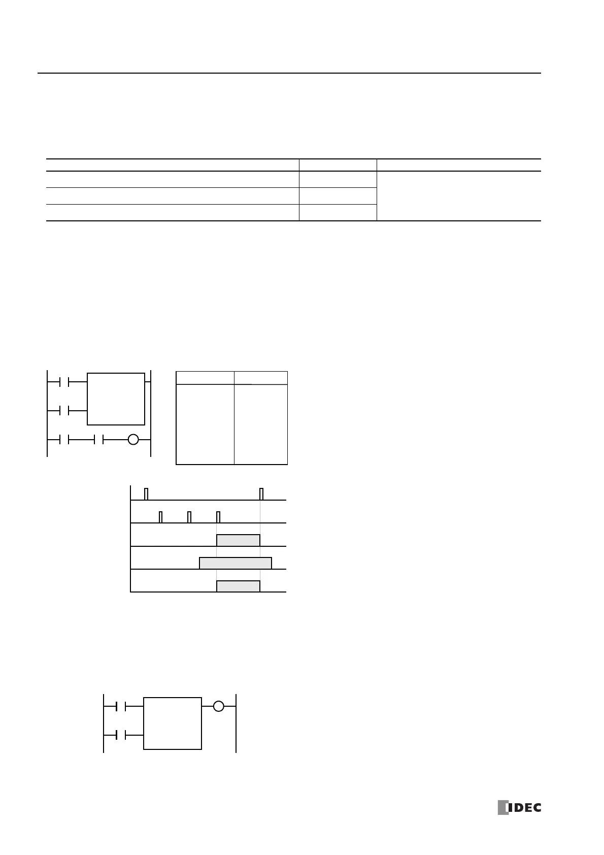
Ladder Diagram
I2
Reset Input I0
ON
OFF
Pulse Input I1
ON
OFF
Counter C0
ON
OFF
Timing Chart
Output Q0
ON
OFF
99998
Input I2
• • •
C0
99999 100000
ON
OFF
CNTD C0
100000
I1
Reset
Pulse
I0
• The preset value 0 through 4,294,967,295 can be designated
using a data register D0 through D1998; then the data of the data
registers becomes the preset value.
• Directly after the CNTD instruction, the OUT, OUTN, SET, RST,
TML, TIM, TMH, TMS, TMLO, TIMO, TMHO, or TMSO instruction
can be programmed.
Q0
CNTD C28
D5
I1
Reset
Pulse
I0 Q0
LOD
LOD
CNTD
LOD
AND
OUT
Instruction Data
I0
I1
C0
100000
I2
C0
Q0
Program List

 Loading...