FC6A S
ERIES
MICROS
MART
L
ADDER
P
ROGRAMMING
M
ANUAL
FC9Y-B1726 4-17
4: B
ASIC
I
NSTRUCTIONS
CDPD (Double-Word Dual-Pulse Reversible Counter)
The double-word dual-pulse reversible counter CDPD has up and down pulse inputs, so the three inputs are required. The circuit
for a double-word dual-pulse reversible counter must be programmed in the following order: preset input, up-pulse input, down-
pulse input, the CDPD instruction, and a counter number C0 through C510, followed by a counter preset value from 0 to
4,294,967,295.
The preset value can be designated using a constant or a data register. When a data register is used, the double-word data of two
consecutive data registers becomes the preset value. For 32-bit data storage setting, see Chapter 5 "32-bit Data Storage Setting"
in the "FC6A Series MICROSmart User’s Manual".
• Double-word counter instructions use two consecutive
counters, and counters cannot be used more than once in
a user program.
• The preset input must be turned on initially so that the
current value returns to the preset value.
• The preset input must be turned off before counting may
begin.
• When the up and down pulses are on simultaneously, no
pulse is counted.
• The counter output is on only when the current value is 0.
• After the current value reaches 0 (counting down), it
changes to 4,294,967,295 on the next count down.
• After the current value reaches 4,294,967,295 (counting
up), it changes to 0 on the next count up.
• When power is off, the counter’s current value is held, and
can also be designated as “clear” type counters using the
Function Area Settings (see Chapter 5 "Memory Backup"
in the "FC6A Series MICROSmart User’s Manual".).
• Counter preset and current values can be changed using
WindLDR without downloading the entire program to the
CPU again. From the WindLDR menu bar, select Online >
Monitor > Monitor, then Online > Custom > New
Custom Monitor. To change a counter preset value,
select DEC(D) in the pull-down list box.
• When the preset or current value is changed during
counter operation, the change becomes effective
immediately.
• When power is off, the changed preset values are cleared
and the original preset values are loaded.
• For data movement when changing, confirming, and
clearing preset values, see "Changing, Confirming, and
Clearing Preset Values for Timers and Counters" on page
4-19.
• WindLDR ladder diagrams show CP (counter preset value)
and CC (counter current value) in advanced instruction
devices. The CNPD instruction cannot be used in an
interrupt program.
• If used, a user program execution error will result, turning
on special internal relay M8004 and the ERR LED on the
FC6A Series MICROSmart. For details about the user
program execution errors, see "User Program Execution
Errors" on page 3-10.
100000 100000
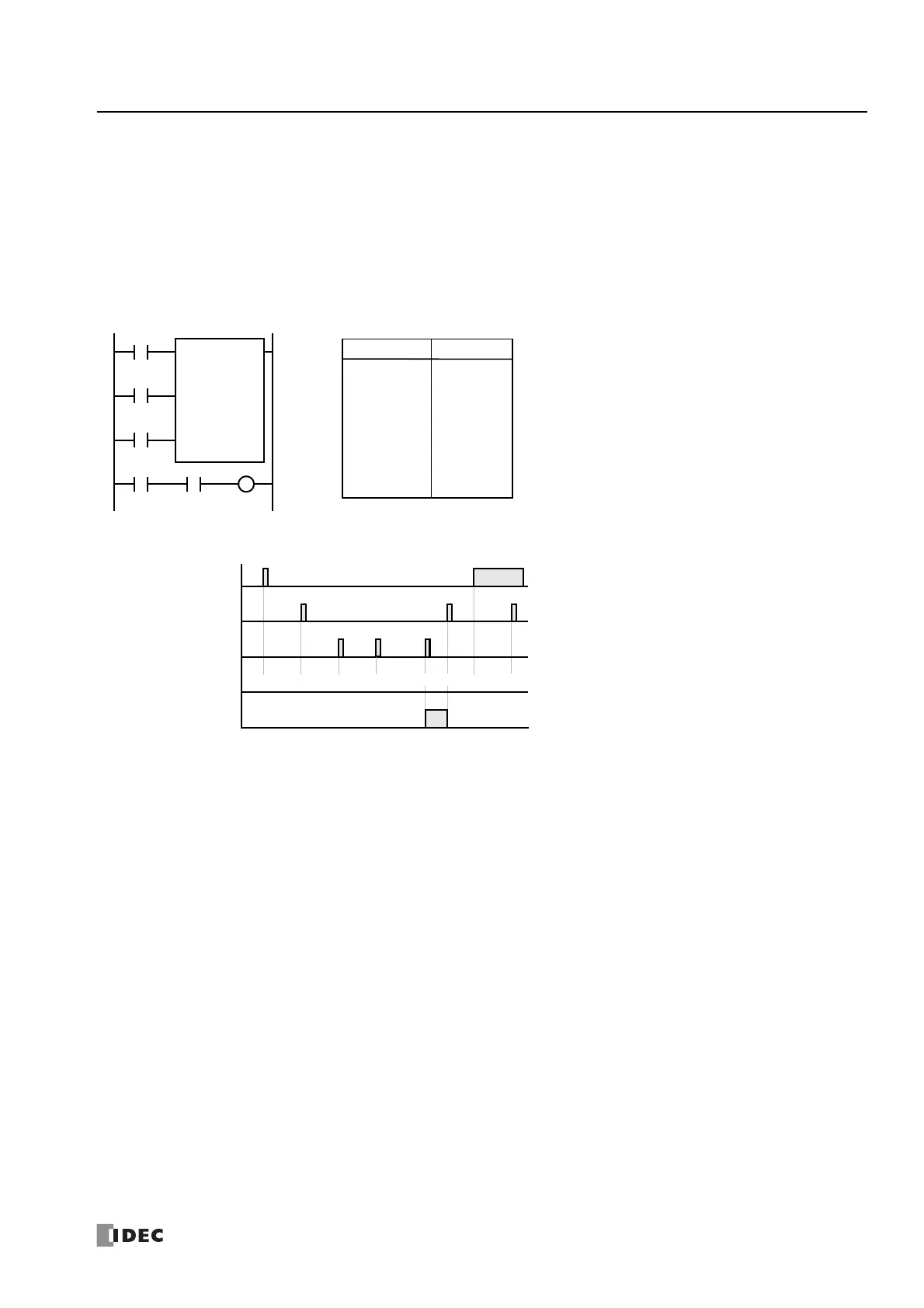
Ladder Diagram
Preset Input I0
ON
OFF
Up Pulse I1
ON
OFF
Down Pulse I2
ON
OFF
Timing Chart
Counter C2
ON
OFF
100000 100001
Counter C2 Value
100000
01
• • •
• • •
I0
I1
CDPD C2
100000
I2
Preset Input
Up Pulse
Down Pulse
I3 C2 Q1
99999
LOD
LOD
LOD
CDPD
LOD
AND
OUT
Instruction Data
I0
I1
I2
C2
100000
I3
C2
Q1
Program List

 Loading...