FC6A S
ERIES
MICROS
MART
L
ADDER
P
ROGRAMMING
M
ANUAL
FC9Y-B1726 4-25
4: B
ASIC
I
NSTRUCTIONS
Setting and Resetting Shift Register Bits
Reset Input I0
ON
OFF
Pulse Input I1
ON
OFF
Data Input I2
ON
OFF
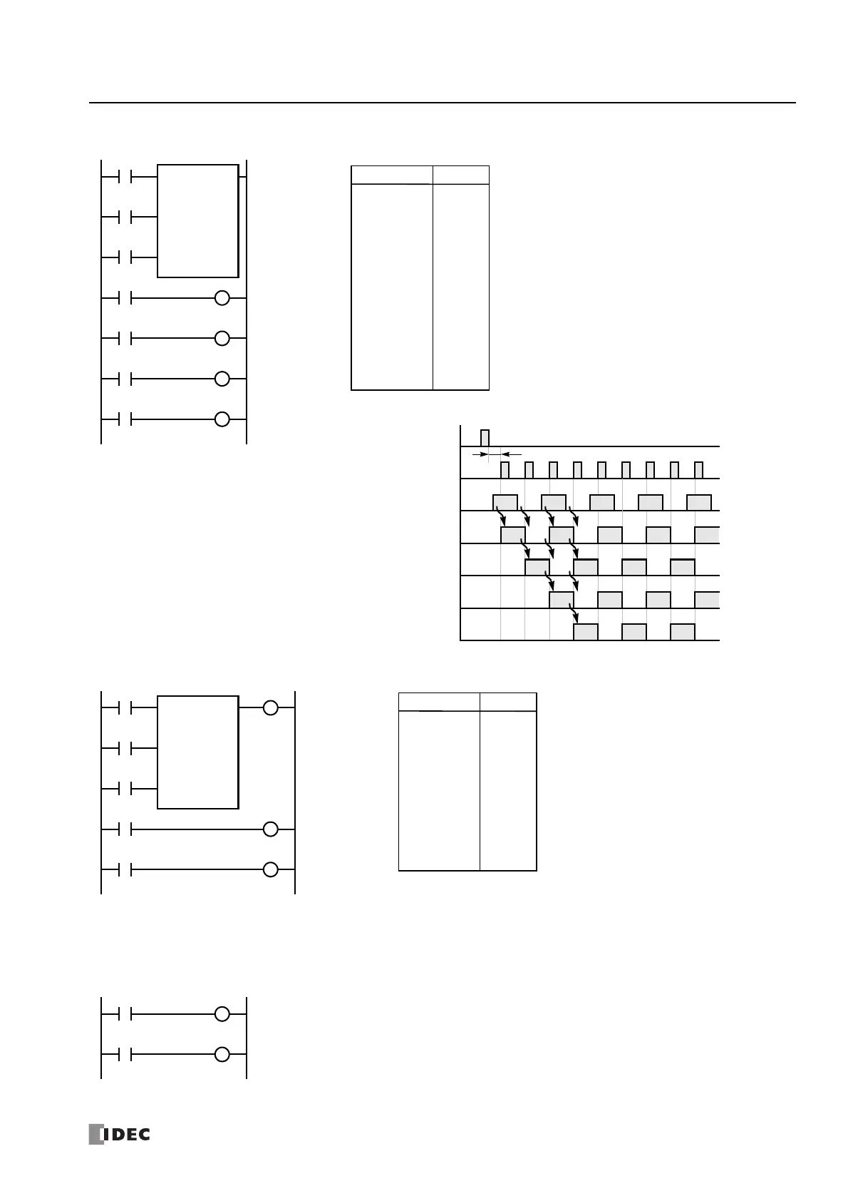
Timing Chart
R1/Q1
ON
OFF
One or more scans are required
R0/Q0
ON
OFF
R3/Q3
ON
OFF
R2/Q2
ON
OFF
Ladder Diagram
I0
I1
SFR R0
4
I2
Reset
Pulse
Data
R0
R1
R2
R3
Q0
Q1
Q2
Q3
LOD
LOD
LOD
SFR
LOD
OUT
LOD
OUT
LOD
OUT
LOD
OUT
I0
I1
I2
R0
4
R0
Q0
R1
Q1
R2
Q2
R3
Q3
Instruction Data
Program List
• The last bit status output can be programmed directly after the SFR
instruction. In this example, the status of bit R3 is read to output Q3.
• Each bit can be loaded using the LOD R# instruction.
Ladder Diagram
I1
I2
SFR R0
4
I3
Reset
Pulse
Data
R0
R1
Q0
Q1
Q3
LOD
LOD
LOD
SFR
OUT
LOD
OUT
LOD
OUT
I1
I2
I3
R0
4
Q3
R0
Q0
R1
Q1
Instruction Data
Program List
• Any shift register bit can be turned on using the SET instruction.
• Any shift register bit can be turned off using the RST instruction.
• The SET or RST instruction is actuated by any input condition.

 Loading...