5: M
OVE
I
NSTRUCTIONS
5-2 FC6A S
ERIES
MICROS
MART
L
ADDER
P
ROGRAMMING
M
ANUAL
FC9Y-B1726
Examples: MOV
Data Type: Word
Data Type: Word
Data move operation for integer data is the same as for word data.
Data Type: Double Word
Data move operation for the long data type is the same as for the double-word data type.
Data Type: Word
Data Type: Double Word
Double-word Data Move in Data Registers
When a data register, timer, or counter is selected as a double-word device, the upper-word data is loaded from or stored to the
first device selected. The lower-word data is loaded from or stored to the subsequent device.
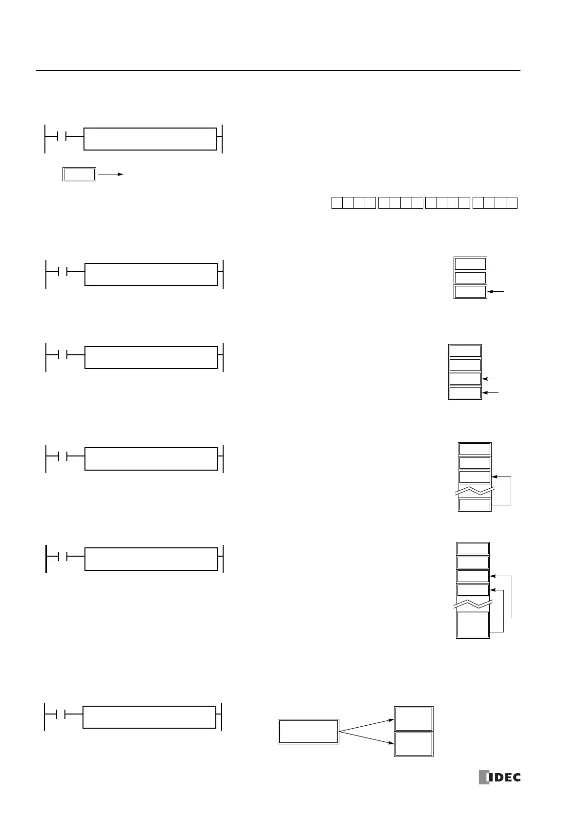
D10 → M0
When input I2 is on, data in data register D10 assigned by source device S1 is moved to
16 internal relays starting with M0 assigned by destination device D1.
Data in the source data register is converted into 16-bit binary data, and the ON/
OFF statuses of the 16 bits are moved to internal relays M0 through M7 and M10
through M17. M0 is the LSB (least significant bit). M17 is the MSB (most significant
bit).
12345
D10 M0 through M7, M10 through M17
0 1 0010 0 0 0 1 0010 1 1
MSB
M0
LSB
M17 M7M10
810 → D2
When input I0 is on, constant 810 assigned by source
device S1 is moved to data register D2 assigned by
destination device D1.
810 → D2·D3
When input I0 is on, constant 810 assigned by source
device S1 is moved to data registers D2 and D3 assigned
by destination device D1.
D10 → D2
When input I1 is on, data in data register D10 assigned
by source device S1 is moved to data register D2
assigned by destination device D1.
D10·D11 → D2·D3
When input I1 is on, data in data registers D10 and D11
assigned by source device S1 is moved to data registers
D2 and D3 assigned by destination device D1.
D1
D0
D2
Double-
D10
D3
D11
word
Data
305419896
Double-word
(12345678h)
High Word D0
4660
(1234h)
Low Word D1
22136
(5678h)
I1
REPS1 –
305419896
D1 –
D0
MOV(D)
Source Data
Data Move to Data Registers
Double-word Destination Device: Data Register

 Loading...