FC6A S
ERIES
MICROS
MART
L
ADDER
P
ROGRAMMING
M
ANUAL
FC9Y-B1726 11-15
11: W
EEK
P
ROGRAMMER
I
NSTRUCTIONS
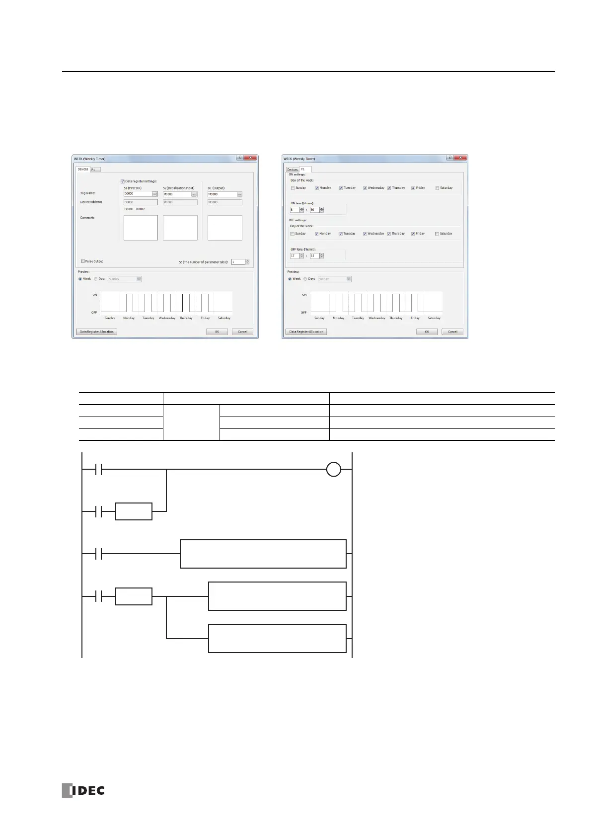
[To indirectly specify the settings with data registers]
This example describes turning on output M0100 Monday to Friday each week from 8:30 to 17:15 as an example.
Select the Data register settings check box and set S1 to D0000 and S2 to M0000.
Parameter tab
Data register allocation
The settings on the P 1 tab are allocated to data registers D0 to D2 as shown in the table below. The settings configured on the
parameter tab are stored in D0 to D2 by turning on initialization input S2.
Data Register Setting Initial Setting
D0
P 1 tab
Day of the week setting 15934 (Monday to Friday, both ON settings and OFF settings)
D1 ON time 830
D2 OFF time 1715
SOTU
M0
SOTU
REPS1 -
900
MOV(W) D1 -
D1
M8120
REPS1 -
1700
D1 -
D2
M1
D1
M100
S2
M0
WEEK S1
D0
S3
1
M8125
M10
MOV(W)
• The initialization input (M1) turns on with the first
scan and the initial settings configured on the P 1
tab are stored in D0 to D2.
• The WEEK instruction starts operating according to
the values of data registers D0 to D2.
• When M10 turns on, the ON time (D1) changes to
9:00 and the OFF time (D2) changes to 17:00.
• When M1 turns on, all of the WEEK instruction
settings (D0 to D2) return to the initial settings.

 Loading...