18: P
ULSE
O
UTPUT
I
NSTRUCTIONS
18-22 FC6A S
ERIES
MICROS
MART
L
ADDER
P
ROGRAMMING
M
ANUAL
FC9Y-B1726
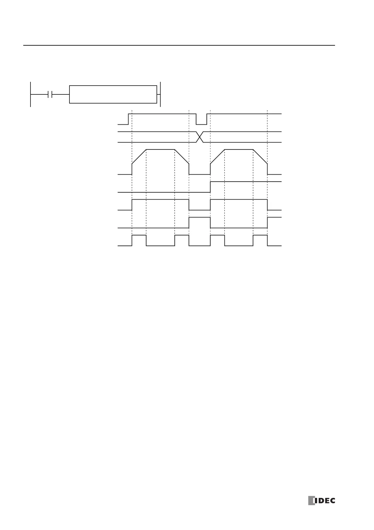
RAMP1 instruction (reversible control enabled, single-pulse output mode) timing chart
RAMP1 instruction, S1 is specified as D0200, D1 is specified as internal relay M0050
When the RAMP instruction input is on, pulses are output according to the settings configured by the control registers. The
reversible control signal is output from Q2. When pulse output starts, M0050 turns on. M0052 turns on while the pulse frequency
is increasing or decreasing. Pulses are output so that the frequency reaches the steady pulse frequency from the initial pulse
frequency in the frequency change time. When the frequency change time is specified as 100, the steady pulse frequency is
reached in 100 ms by increasing or decreasing the frequency every 10 ms.
Pulse output stops when the pulses configured by the preset value are output. (The number of pulses is also counted while
changing the frequency.) At this time, M0050 turns off and M0051 turns on.
If the RAMP instruction input turns off during pulse output, pulse output is canceled. If this input turns on again, the operation
starts from the beginning. Even if the contents of the data registers are changed during pulse output, the change is not reflected
in the pulse output operation. The changed content is reflected the next time the RAMP instruction is started.
D1
M0050
S2
M0000
RAMP
1
S1
D0200
RAMP instruction
input
RAMP instruction input
Pulse frequency Q0
Pulse output ON M0050
Pulse output complete M0051
Pulse output status M0052
Control direction D0203 0 (Forward) 1 (Reverse)
Reversible control
signal
Q2

 Loading...