18: P
ULSE
O
UTPUT
I
NSTRUCTIONS
18-42 FC6A S
ERIES
MICROS
MART
L
ADDER
P
ROGRAMMING
M
ANUAL
FC9Y-B1726
15. Deceleration time
This setting specifies the time to decrease the pulse frequency.
Set the time between 10 and 10,000 ms in increments of 1 ms. The first digit of the setting is handled as zero. For example, if
144 is entered, the set value is handled as 140 ms.
16. Trigger to start monitoring origin input
Specifies the timing to start the origin signal monitor.
17. Reversible control enable
Selects the reversible control method from the following reversible control modes when ZRN mode 1 is selected for 9. Zero
return method. (This is an example when ZRN1 is used with the All-in-One CPU module.)
The outputs used on the FC6A Series MICROSmart vary based on the instruction used, the combination of the pulse output
mode and reversible control, and the model used.
Note: The outputs (pulse output and reversible control output) used by ZRN instruction cannot be used by other instructions simultaneously.
18. Control direction
When reversible control is enabled, store 0 in this data register for forward operation and store 1 in this data register for reverse
operation.
Timing Description
Proximity signal OFF→ON After the proximity signal changes from off to on, the change from off to on in the origin signal is monitored.
Proximity signal ON→OFF
After the proximity signal changes from off to on and then next changes from on to off, the change from off
to on in the origin signal is monitored.
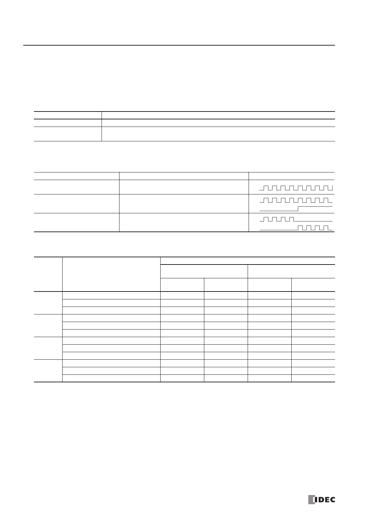
Reversible Control Enable Operation Pattern
Reversible control disabled
Select this option when using pulse output in a single
direction. Pulse A and pulse B can be used independently.
Reversible control Single-pulse
output
Pulse A is used as pulse output. Pulse B on/off is used as
reversible control.
Reversible control Dual-pulse
output
Pulse A is used as forward pulse (CW) output.Pulse B is
used as reverse pulse (CCW) output.
Command Operating Condition
Output Used
All-in-One CPU Module
CAN J1939 All-in-One CPU
Module/Plus CPU Module
Pulse Output
Reversible
Control Output
Pulse Output
Reversible
Control Output
ZRN1
Reversible control disabled Q0 — Q0 —
Reversible control Single-pulse output mode Q0 Q2 Q0 Q1
Reversible control Dual-pulse output mode Q0, Q1 — Q0, Q1 —
ZRN2
Reversible control disabled Q1 — Q2 —
Reversible control Single-pulse output mode Q1 Q3 Q2 Q3
Reversible control Dual-pulse output mode — — Q2, Q3 —
ZRN3
Reversible control disabled Q2 — Q4 —
Reversible control Single-pulse output mode — — Q4 Q5
Reversible control Dual-pulse output mode — — Q4, Q5 —
ZRN4
Reversible control disabled Q3 — Q6 —
Reversible control Single-pulse output mode — — Q6 Q7
Reversible control Dual-pulse output mode — — Q6, Q7 —
Q0
Q2

 Loading...