18: P
ULSE
O
UTPUT
I
NSTRUCTIONS
18-44 FC6A S
ERIES
MICROS
MART
L
ADDER
P
ROGRAMMING
M
ANUAL
FC9Y-B1726
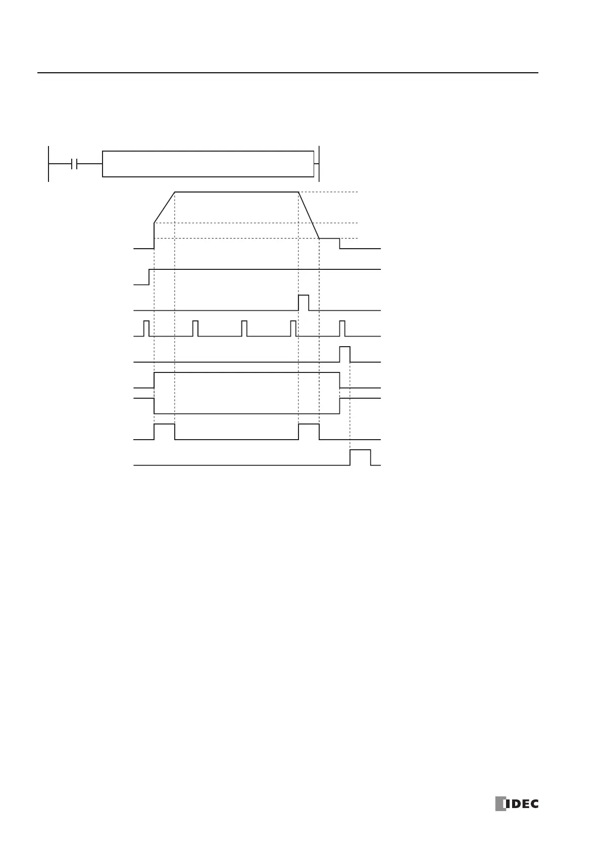
ZRM Mode 1 (When Using the Proximity Signal and Origin Signal) Timing Chart
ZRN1 instruction, S1 is specified as data register D0200, S3 is specified as external input I2, D1 is specified as internal
relay M0010
• When the ZRN1 instruction changes from off to on, pulses are output at the initial pulse frequency, and then pulses are output so that the
frequency reaches the steady pulse frequency from the initial pulse frequency in the frequency change time. When the frequency change
time is specified as 100, the steady pulse frequency is reached in 100 ms by increasing or decreasing the frequency every 10 ms.
• When pulse output starts, M0010 turns on and M0011 turns off.
• While the pulse speed is increasing or decreasing, M0012 turns on.
• When I2 changes from off to on, the pulse speed starts to decrease and reaches the creep pulse frequency.
• When I3 is detected as changing from off to on, pulse output stops.
• When pulse output stops, M0100 turns on. M0100 turns on for one scan or longer but less than two scans.
• When M0100 changes from on to off and the zero return operation has completed, M0013 turns on.
• Then when pulse output stops, M0010 turns off and M0011 turns on.
• If the ZRN1 instruction input turns off during pulse output, pulse output stops. If the input turns on again, the operation starts from the
beginning.
• Even if the contents of the data registers are changed during pulse output, the change is not reflected in pulse output operation. The
changed content is reflected the next time the ZRN1 instruction is started.
S4
I0003
S2
M0000
ZRN
1
S1
D0200
ZRN instruction
input
ZRN1 instruction input
Pulse output ON M0010
Pulse output
complete
M0011
Proximity signal I2
Pulse frequency Q0
S3
I0002
Steady pulse frequency
Creep pulse frequency
Pulse output
status
M0012
D2
M0100
D1
M0010
Initial pulse frequency
Origin signal I3
Complete signal M0100
Zero return
complete
M0013

 Loading...