19: PID C
ONTROL
I
NSTRUCTION
19-10 FC6A S
ERIES
MICROS
MART
L
ADDER
P
ROGRAMMING
M
ANUAL
FC9Y-B1726
Notes:
• Alarm action point
This indicates the point where the alarm output changes from OFF to ON.
• Standby function
This function does not immediately turn ON the alarm output when starting execution of the PIDA instruction, even when the process
variable is in the alarm output ON range.
The standby function is canceled when the process variable enters the alarm output OFF range, and when the process variable enters the
alarm output ON range, the alarm output will turn ON.
If the set point is changed, the standby function will be enabled again.
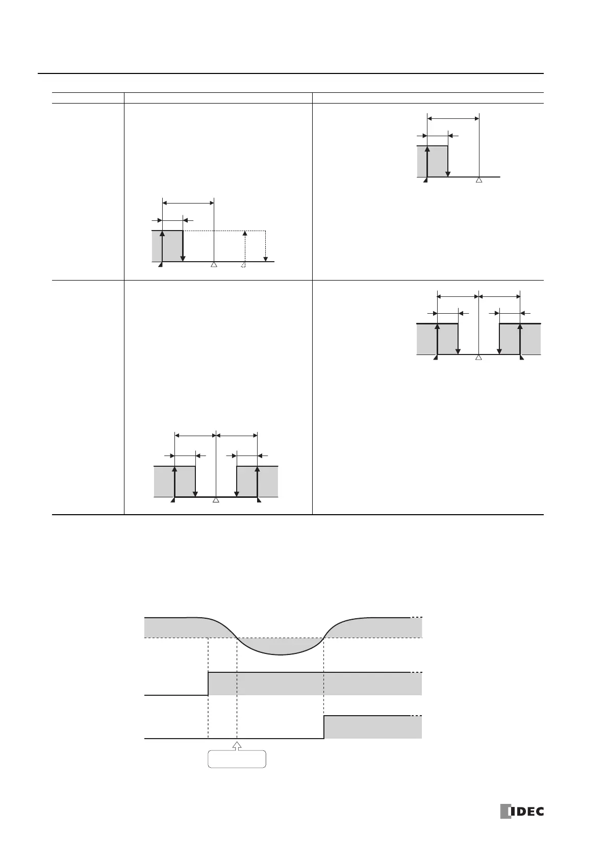
Lower Limit Alarm
with Standby
Turns ON the alarm output when process variable ≤
(set point + alarm value).
Turns OFF the alarm output when process variable ≥
(set point + alarm value + hysteresis).
When (set point + alarm value) < process variable <
(set point + alarm value + hysteresis), the alarm
output maintains the state of the previous scan.
The gray-colored portion is where the standby
function operates.
Set point: 200.0°C
Alarm value: -5.0°C
Hysteresis: 2.0°C
When process variable ≤ 195
.0
°C, the alarm output is turned ON.
When process variable ≥ 197
.0
°C, the alarm output is turned OFF.
Upper/Lower Limit
Alarm with Standby
Turns ON the alarm output when process variable ≥
(set point + alarm value).
Turns ON the alarm output when process variable ≤
(set point - alarm value).
Turns OFF the alarm output when (set point - alarm
value + hysteresis) ≤ process variable ≤ (set point +
alarm value - hysteresis).
When (set point + alarm value - hysteresis) < process
variable < (set point + alarm value), the alarm output
maintains the state of the previous scan.
When (set point - alarm value) < process variable <
(set point - alarm value + hysteresis), the alarm
output maintains the state of the previous scan.
The gray-colored portion is where the standby
function operates.
Set point: 200.0°C
Alarm value: 5.0°C
Hysteresis: 2.0°C
When process variable ≥ 205
.0
°C, the alarm output is turned ON.
When process variable ≤ 195
.0
°C, the alarm output is turned ON.
When 197.0°C ≤ process variable ≤ 203.0°C, the alarm output is
turned OFF.
Type Action Example
OFF
ON
+ Alarm action pointSet point
Hysteresis
Alarm value
-
Alarm action point
OFF
ON
195.0°C 197.0°C 200.0°C
2.0°C
5.0°C
ON
Alarm action pointSet pointAlarm action point
HysteresisHysteresis
Alarm value Alarm value
OFF
ON
195.0°C 205.0°C197.0°C 203.0°C200.0°C
2.0°C
5.0°C
2.0°C
5.0°C
ON
OFF
Alarm output
ON
(Alarm output ON range) (Alarm output ON range)
(Alarm output OFF range)
OFF
PID instruction input
Process variable
Cancel standby

 Loading...