19: PID C
ONTROL
I
NSTRUCTION
19-14 FC6A S
ERIES
MICROS
MART
L
ADDER
P
ROGRAMMING
M
ANUAL
FC9Y-B1726
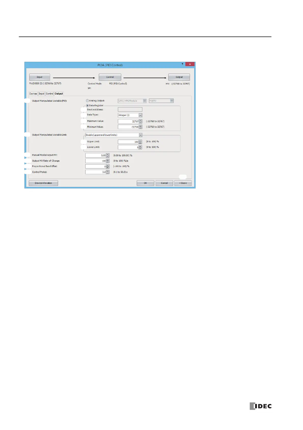
■Output tab
This tab configures the output parameters for the PIDA instruction.
1. Output Manipulated Variable (analog value) (S1+19)
Set the output for the PID control. The value can be selected as Analog Output or Data Register. The manipulated variable
calculated with the PIDA instruction according to the output manipulated variable limit (6) setting is stored.
When Analog Output is specified
Configure the module with the analog output you want to configure as the output manipulated variable (analog value)
destination and its analog number.
• For auto mode, the analog value stored in the output manipulated variable (S1+19) undergoes linear conversion in the range of
the maximum value and the minimum value of the analog output and is output.
• For manual mode, the value stored in the manual mode output manipulated variable (S1+17) undergoes linear conversion in the
range of the maximum value and the minimum value of the analog output and is output.
For switching between auto/manual mode, see "Auto/manual mode (S3+1)" on page 19-21.
The value of the output manipulated variable is automatically stored in the special data register that corresponds to the
analog output.
For allocating special data registers, see "Special Internal Relay Device Addresses" on page 2-4.
Note: To use an analog output, the analog output must be configured in advance.
For details on analog output settings, see Chapter 9 "Analog I/O Modules" in the "FC6A Series MICROSmart User’s Manual".
When Data Register is specified
Specify the device to store the output manipulated variable.
• For auto mode, the output manipulated variable for PID control is stored in output manipulated variable (analog value) (S1+19)
for the control register.
• It is stored in the range of minimum value (5) ≤ output manipulated variable ≤ maximum value (4).
• For manual mode, the stored value is that the one, stored in the manual
mode output manipulated variable (S1+17), is converted linearly in the range of minimum value (5) and maximum value (4).
Configure parameters 2. Device Address through 5. Minimum Value when data register is selected as the process variable.
2. Device Address
Shows the control register (S1+19) configured on the devices tab when Data Register is specified as the output manipulated
variable (1).
3. Data Type
Select the output manipulated variable (1) data type as W (word) or I (integer).
Analog Module Configure: Select the analog output module.
Select the module as the CPU module, HMI module, or expansion module 1 to 15.
Analog Output No.: Select the output number on the analog output module.
Select as AQ0 to AQ7.
1.
6.
9.
10.
11.
12.
2.
3.
4.
5.
7.
8.
13.

 Loading...