FC6A S
ERIES
MICROS
MART
L
ADDER
P
ROGRAMMING
M
ANUAL
FC9Y-B1726 2-9
2: D
EVICES
Supplementary Descriptions of the Special Internal Relays
■ M8000: Start Control
M8000 controls the run/stop status of the FC6A Series MICROSmart. The CPU is set to run when M8000 is turned on, and the
CPU is set to off when M8000 is turned off. See "Start/Stop Operation" on page 1-18. However, the function switch, stop input,
and reset input have precedence over start control. M8000 maintains its status when the CPU is powered down. When data to
be maintained during a power failure disappears after the CPU has been off for a period longer than the battery backup
duration, the CPU restarts operation as selected in Configuration > Run/Stop Control > Run/Stop Selection at Keep Data Error.
For details, see Chapter 5 "Run/Stop Selection at Keep Data Error" in the "FC6A Series MICROSmart User’s Manual".
■ M8001: 1-s Clock Reset
While M8001 is on, M8121 (1-s clock) is always off.
■ M8002: All Outputs OFF
While M8002 is on, all outputs are off. The self-holding circuit created in the ladder program is also off.
■ M8003: Carry/Borrow
When a carry (Cy) or borrow (Bw) results from executing an addition or subtraction instruction, M8003 is turned on. For details,
see "Carry and Borrow" on page 3-10".
■ M8004: User Program Execution Error
When an error occurs while executing a user program, M8004 is turned on. For details on user program execution errors, see
"User Program Execution Error" on page A-12.
■ M8005: Communication Error
When an error occurs during data link communication, M8005 is turned on. The state is retained even when the error is cleared.
■ M8006: Communication Prohibited Flag (When Data Link Master)
During data link communication, communication is stopped while M8006 is on.
■ M8007: Initialization Flag (When Data Link Master)/Stop Communication Flag (When Data Link Slave)
■ M8010: Status LED Operation
While M8010 is on, the status LED [STAT] is turned on. While off, the status LED [STAT] is turned off.
M8384 User Communication Receive Instruction Cancel Flag (Port 25) Cleared Cleared R/W
M8385 User Communication Receive Instruction Cancel Flag (Port 26) Cleared Cleared R/W
M8386 User Communication Receive Instruction Cancel Flag (Port 27) Cleared Cleared R/W
M8387 User Communication Receive Instruction Cancel Flag (Port 28) Cleared Cleared R/W
M8390 User Communication Receive Instruction Cancel Flag (Port 29) Cleared Cleared R/W
M8391 User Communication Receive Instruction Cancel Flag (Port 30) Cleared Cleared R/W
M8392 User Communication Receive Instruction Cancel Flag (Port 31) Cleared Cleared R/W
M8393 User Communication Receive Instruction Cancel Flag (Port 32) Cleared Cleared R/W
M8394 User Communication Receive Instruction Cancel Flag (Port 33) Cleared Cleared R/W
M8395 to
M8447
— Reserved — — — —
M8450 BACnet Communication Bit Operating Cleared R/W
M8451 to
M8597
— Reserved — — — —
M8600
High-speed Counter (Group 3/I3)
Reset Status Maintained Cleared R
M8601 Underflow Maintained Cleared R
M8602 Count Direction Flag Maintained Cleared R
M8603 to
M8997
— Reserved — — — —
When data link master: When this flag is turned on in the run status, the data link is initialized just once to check the connection
status. Use this when the slave configured in the data link is powered at a timing slower than the
master.
When data link slave : This flag is turned on when communication from the master is interrupted for 10 s or longer. This flag is
turned off when communication can be normally received.
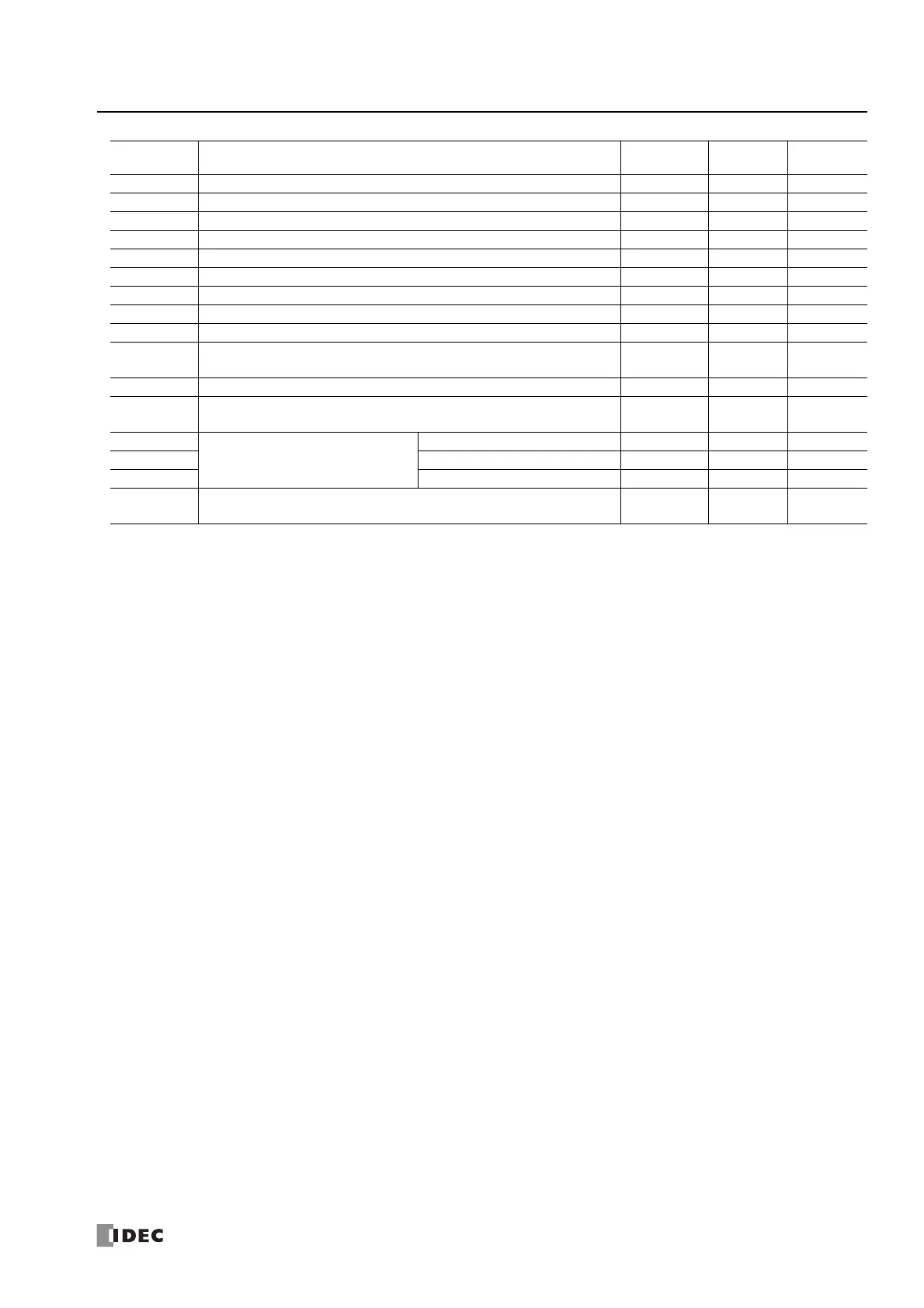
Device
Address
Description
When
Stopped
Power
OFF
R/W

 Loading...