19: PID C
ONTROL
I
NSTRUCTION
19-28 FC6A S
ERIES
MICROS
MART
L
ADDER
P
ROGRAMMING
M
ANUAL
FC9Y-B1726
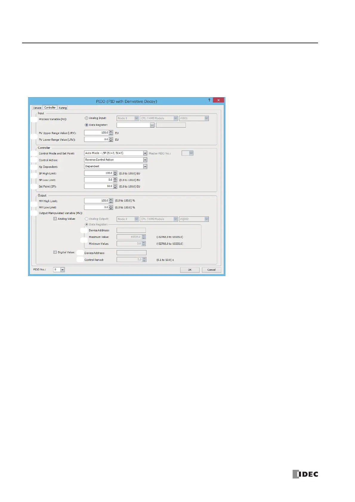
■Controller tab
This tab is used to configure the control parameters of the PIDD instruction.
To store the initial settings of the PIDD instruction that are set on the Controller tab in the control registers and control relays,
turn on the initialization input for the corresponding PIDD instruction after the user program is downloaded to the FC6A Series
MICROSmart.
1. Process Variable (PV) (S1+0, S1+1)
Select Analog Input or Data Register as the process variable (PV) for PID control.
When Analog Input is specified
A built-in analog input in the CPU or an analog input of the analog I/O cartridge or analog I/O module can be selected as the
process variable (PV) of the PIDD instruction. Specify the analog input with the module and analog input number.
Node: Select the node of the module having the analog input to specify.
Node 0:
Plus CPU module/Expansion interface remote master module
Node 1 to 10:
Expansion interface remote slave module
Module: Select the module having the analog input to specify.
CPU/HMI Module: Built-in analog input, analog I/O cartridge
Expansion Module 1 to 15: Analog I/O module
Analog Input No.: Select the analog input number from AI0 to AI7.
1.
2.
3.
4.
5.
6.
7.
8.
9.
10.
11.
12.
13.

 Loading...