20: D
UAL
/ T
EACHING
T
IMER
I
NSTRUCTIONS
20-2 FC6A S
ERIES
MICROS
MART
L
ADDER
P
ROGRAMMING
M
ANUAL
FC9Y-B1726
Valid Devices
For valid device address ranges, see "Device Addresses" on page 2-1.
Special internal relays cannot be designated as D1.
Destination device D2 (system work area) uses 2 data registers starting with the device designated as D2. The two data registers are used for a
system work area. Do not use these data registers for destinations of other advanced instructions, and do not change values of these data registers
using the monitor function on WindLDR. If the data in these data registers are changed, the dual timer does not operate correctly.
The dual timer instructions cannot be used in an interrupt program. If used, a user program execution error will result, turning on special internal
relay M8004 and the ERR LED on the FC6A Series MICROSmart.
When a user program execution error occurs, the execution of the instruction is canceled and the next instruction is executed. The data in D1
(destination 1) is unchanged. For details about the user program execution errors, see "User Program Execution Errors" on page 3-10.
Examples: DTML, DTIM, DTMH, DTMS
For the timer accuracy of timer instructions, see "TML, TIM, TMH, and TMS (Timer)" on page 4-7.
Device Function I Q M R T C D P Constant
S1 (Source 1) ON duration — — — — — — X — 0-65,535
S2 (Source 2) OFF duration — — — — — — X — 0-65,535
D1 (Destination 1) Dual timer output — X X — — — — —
D2 (Destination 2) System work area —————— X — —
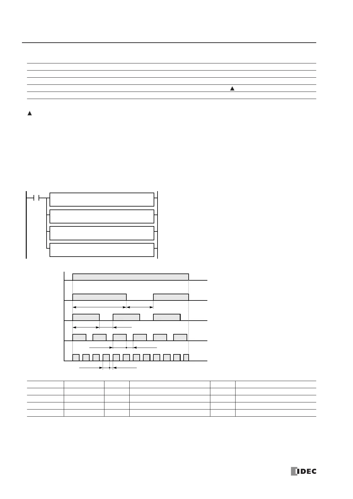
While input I0 is on, four dual timer instructions turn on and off the
destination devices according to the on and off durations assigned by source
devices S1 and S2.
I0
D2
D100
S1
2
D1
M10
DTML S2
1
D2
D200
S1
10
D1
M20
DTIM S2
5
D2
D300
S1
50
D1
M30
DTMH S2
25
D2
D400
S1
250
D1
M40
DTMS S2
125
Instruction Increments S1 ON Duration S2 OFF Duration
DTML 1 s 2 1 s × 2 = 2 s 1 1 s × 1 = 1 s
DTIM 100 ms 10 100 ms × 10 = 1 s 5 100 ms × 5 = 0.5 s
DTMH 10 ms 50 10 ms × 50 = 500 ms 25 10 ms × 25 = 250 ms
DTMS 1 ms 250 1 ms × 250 = 250 ms 125 1 ms × 125 = 125 ms
500 ms 250 ms
M10
ON
OFF
M20
ON
OFF
M30
ON
OFF
I0
ON
OFF
2 s
M40
ON
OFF
1 s
1 s 0.5 s
250 ms 125 ms

 Loading...