23: F
ILE
D
ATA
P
ROCESSING
I
NSTRUCTIONS
23-4 FC6A S
ERIES
MICROS
MART
L
ADDER
P
ROGRAMMING
M
ANUAL
FC9Y-B1726
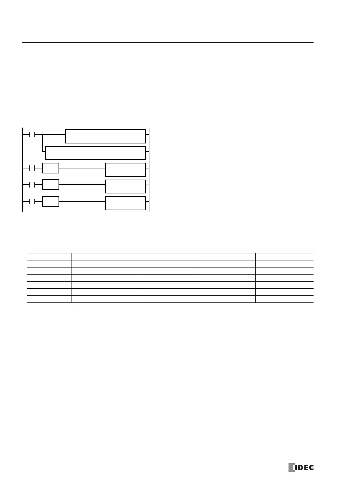
Example: FIFOF, FIEX, and FOEX
This program demonstrates a user program of the FIFOX, FIEX, and FOEX instructions to use an FIFO data file.
FIFO Data File
The table below shows the data stored in FIFO data file 2 when inputs I0, I1, and I2 are turned on in this order. Only valid data
managed by the FIFOF, FIEX, and FOEX instructions are shown in the table.
File number: 2
Quantity of data registers per record: 3
Quantity of records: 4
FIFO Data file: D100 through D113 (3×4+2 data registers)
FIFO status outputs: M100 through M102
M8120 is the initialize pulse special internal relay.
When the CPU starts, MOV sets 0 to FI and FO pointers, and FIFOF initializes
FIFO data file 2.
When input I0 is turned on, the data in D10 through D12 are stored to the
FIFO data file 2.
When input I1 is turned on, the data in D20 through D22 are stored to the
FIFO data file 2.
When input I2 is turned on, the first data is retrieved from the FIFO data file 2
and stored to D50 through D52.
I0
S1
D10
FIEX(W)
2
M8120
SOTU
Ladder Diagram
REP
2
S1 –
0
D1 R
D100
MOV(W)
D2
M100
S1
3
D1
D100
FIFOF(W)
2
S2
4
I1
S1
D20
FIEX(W)
2
I2
D1
D50
FOEX(W)
2
SOTU
SOTU
Function Device Address Input I0 Input I1 Input I2
FI Pointer D100 1 2 2
FO Pointer D101 0 0 1
Record 0 D102 through D104 D10, D11, D12 D10, D11, D12 —
Record 1 D105 through D107 — D20, D21, D22 D20, D21, D22
Record 2 D108 through D110 — — —
Record 3 D111 through D113 — — —

 Loading...