26: S
CRIPT
26-4 FC6A S
ERIES
MICROS
MART
L
ADDER
P
ROGRAMMING
M
ANUAL
FC9Y-B1726
Device List
This section shows the devices that can be used in Script Editor and the device notation.
This section describes available devices and its notation that can be used in the Script Editor dialog box.
Note: The device ranges differ depending on each FC6A Series MICROSmart. Specify the devices within the device range of the selected FC6A
Series MICROSmart. For device ranges, see "Device Addresses" on page 2-1.
Calculations in which both bit and word devices are used are not allowed.
Bit devices are always processed as bits, and values of those devices are 0 (OFF) or 1 (ON).
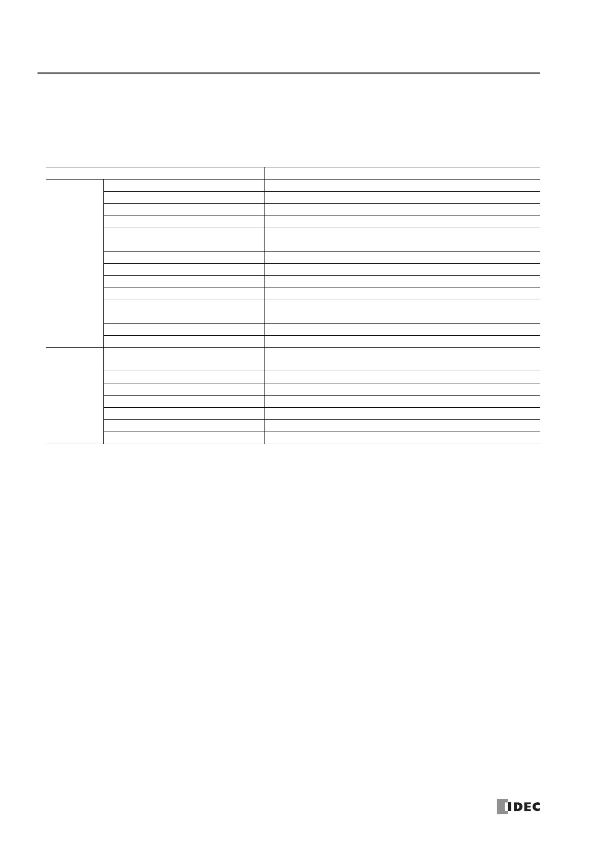
Device Notation in Script Editor
Bit device
I (Inputs) I0 to I27
I (Expansion inputs) I30 to I10597
Q (Outputs) Q0 to Q17
Q (Expansion outputs) Q30 to Q10597
M (Internal relays)
M0000 to M7997,
M10000 to M21247
M (Special internal relays) M8000 to M9997
R (Shift registers) R000 to R255
T (Timer contacts) C000 to C511
C (Counter contacts) T000 to T1999
D (Data register bits)
D0000.0 ... D0000.15 to D7999.0 ... D7999.15
D10000.0 ... D10000.15 to D61999.0 ... D61999.15
D (Special data register bits) DD8000.0 ... D8000.15 to D8899.0 ... D8899.15
D (Non-retentive data register bits) D70000.0 ... D70000.15 to D269999.0 ... D269999.15
Word device
D (Data registers)
D0000 to D7999
D10000 to D61999
D (Special data registers) D8000 to D8899
D (Non-retentive data registers) D70000 to D269999
TC (Timer current values) TC000 to TC1999
TP (Timer preset values) TP000 to TP1999
CC (Counter current values) CC000 to CC511
CP (Counter preset values) CP000 to CP511

 Loading...