2: D
EVICES
2-38 FC6A S
ERIES
MICROS
MART
L
ADDER
P
ROGRAMMING
M
ANUAL
FC9Y-B1726
• Client connection (most significant bit = 0)
0000: Unused
0001: User Communication
0010: Modbus TCP client
0100: User communication UDP
• Server connection (most significant bit = 1)
1000: Maintenance Communication
1001: User Communication
1010: Modbus TCP server
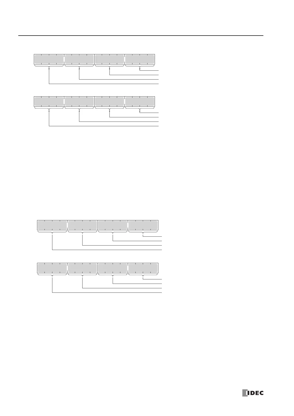
■ D8284, D8285: Communication Mode Information (HMI Connection) (HMI Connection 1 to 8)
D8284: Indicates the communication mode of HMI connections 1 through 4.
D8285: Indicates the communication mode of HMI connections 5 through 8.
The allocation of connections in the device (bit assignment) is as follows.
• Client connection (most significant bit = 0)
0000: Unused
• Server connection (most significant bit = 1)
1000: Maintenance Communication
■ D8303: CPU Module Ethernet Port 1 IP Settings/DNS Settings Switching
The IP settings/DNS settings for Ethernet Port 1 can be changed by writing one of the setting values in the table on the next
page to D8303 and then turning on M8190.
To use this function, enable the following items in Function Area Settings of WindLDR.
• All-in-One CPU module/CAN J1939 All-in-One CPU module
Enable D8303 (IP Settings / DNS Settings switching) on Network Settings in Function Area Settings
• Plus CPU module
Enable D8303 (IP Settings / DNS Settings switching) on Ethernet Port 1 in Function Area Settings
Bit
15
Bit
0
Bit
7
Bit
8
Connection 9
Connection 10
Connection 11
Connection 12
D8760
Bit
15
Bit
0
Bit
7
Bit
8
Connection 13
Connection 14
Connection 15
Connection 16
D8761
Bit
15
Bit
0
Bit
7
Bit
8
HMI Connection 1
HMI Connection 2
HMI Connection 3
HMI Connection 4
D8284
Bit
15
Bit
0
Bit
7
Bit
8
HMI Connection 5
HMI Connection 6
HMI Connection 7
HMI Connection 8
D8285

 Loading...