53
HDK-99 1803 VER1 (E)
3
INSTALLATION and CONNECTION
3.5 CCU Connection
■
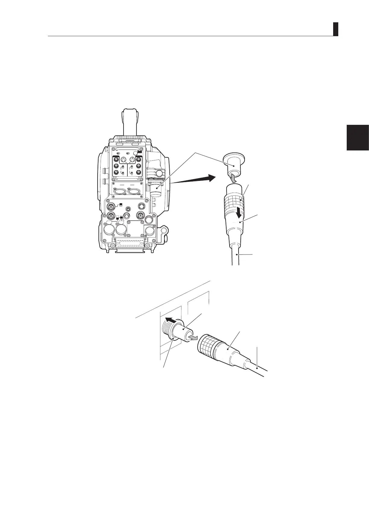
Removing the Fiber Cable
This section explains how to remove the ber cable.
CAUTION:
When you remove the cable, be sure to hold the plug and pull. Failure to do so may damage the ber in the cable.
●
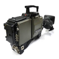
Camera
INCOMENG
PROD
INCOMENG
PROD
MIC-1
MIC-2
DC IN
PGM2
PGM1
MIC
ON
OFF
PTT
PROD
BOTH
ENG
MIC
ON
OFF
PTT
PROD
BOTH
ENG
INCOM
PGM2
PGM1
INCOM
REAR TALLY INCOM SEL
CALL
INCOM1 INCOM2
OFF ACT
FRONT
REAR
1 RET 2
FRONT
INC1 INC2
1
2
4
3
1
2
4
3
Q-TV/GL
EARPHONE
+12V
OFF
+48V
MON
MON SDI
SDI OUT
I/O
DC OUT
Camera rear view
CAMERA connector
(male)
Unlocking ring
Fiber cable
●
CCU
CAMERA connector (female)
Unlocking ring
Plug (male)
1 Remove the cable from the camera while pulling the unlocking ring on the fiber cable plug toward you.
If the connector pins are locked, the ber cable will not be easily removed. If it is locked, push the ber cable toward the
CAMERA connector, and then remove as described above.
2 Remove the cable from the CCU-980 while pushing the unlocking ring of the CAMERA connector on the rear of
CCU-980.
If the connector pins are locked, the ber cable will not be easily removed. If it is locked, push the ber cable toward the
CAMERA connector, and then remove as described above.