51
HDK-99 1803 VER1 (E)
3
INSTALLATION and CONNECTION
3.4 Monitor Connection
3.4 Monitor Connection
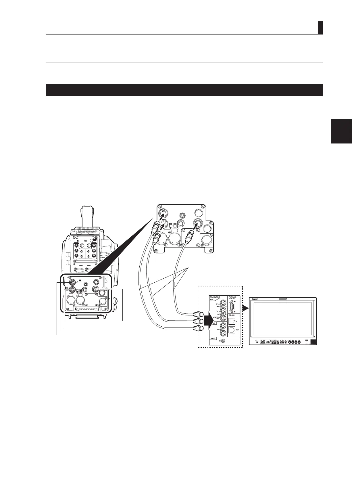
This section explains how to connect the HDK-99 to monitors.
Connecting Camera and Monitor
There are three connectors on the rear of the camera to output various video signals. The type of video signal output from each
connector is different. Be sure to connect to a correct connector via a coaxial cable in accordance with the monitor to be used.
- Q-TV/GL, MON OUT connector : Selection between Q-TV/GL and MON OUT is made by the Q-TV/GL, MON OUT SELECT
switch.
If Q-TV/GL is selected, this connector outputs the Q-TV OUT signal when the camera is
connected to the CCU, or it inputs an external synchronization signal (GENLOCK) when the
camera is used stand-alone.
When MON is selected, this becomes the monitor output of the camera images, and the same
image signals are output as the viewnder.
- SDI OUT connector : Outputs the digital serial video signal. Applicable to the HD-SDI signal (not applicable to the
SD-SDI signal).
- MON SDI connector : Outputs the digital serial video signal. Applicable to the HD-SDI signal (not applicable to the
SD-SDI signal).
MIC-1
MIC-2
+48V
AB+12V
OFF
MON SDI
SDI OUT
DC OUT
EARPHONE
REM
DC IN
I/O
Q-TV/GL
INCOMENG
PROD
INCOMENG
PROD
MIC-1
MIC-2
DC IN
PGM2
PGM1
MIC
ON
OFF
PTT
PROD
BOTH
ENG
MIC
ON
OFF
PTT
PROD
BOTH
ENG
INCOM
PGM2
PGM1
INCOM
REAR TALLYINCOM SEL
CALL
INCOM1 INCOM2
OFFACT
FRONT
REAR
1 RET 2
FRONT
INC1 INC2
1
2
4
3
1
2
4
3
Q-TV/GL
EARPHONE
+12V
OFF
+48V
MON
MON SDI
SDI OUT
I/O
DC OUT
Coaxial cable
MON OUT connector
MON OUT connector
HD SDI OUT connector
rear view