17 Image Vault
®
PRO Command
1 - Short to 4 & 6
2 - Data RX
3 - Open
4 - Short to 1 & 6
5 - Data Ground
6 - Short to 1 & 4
7 - Short to 8
8 - Short to 7
9 - Open
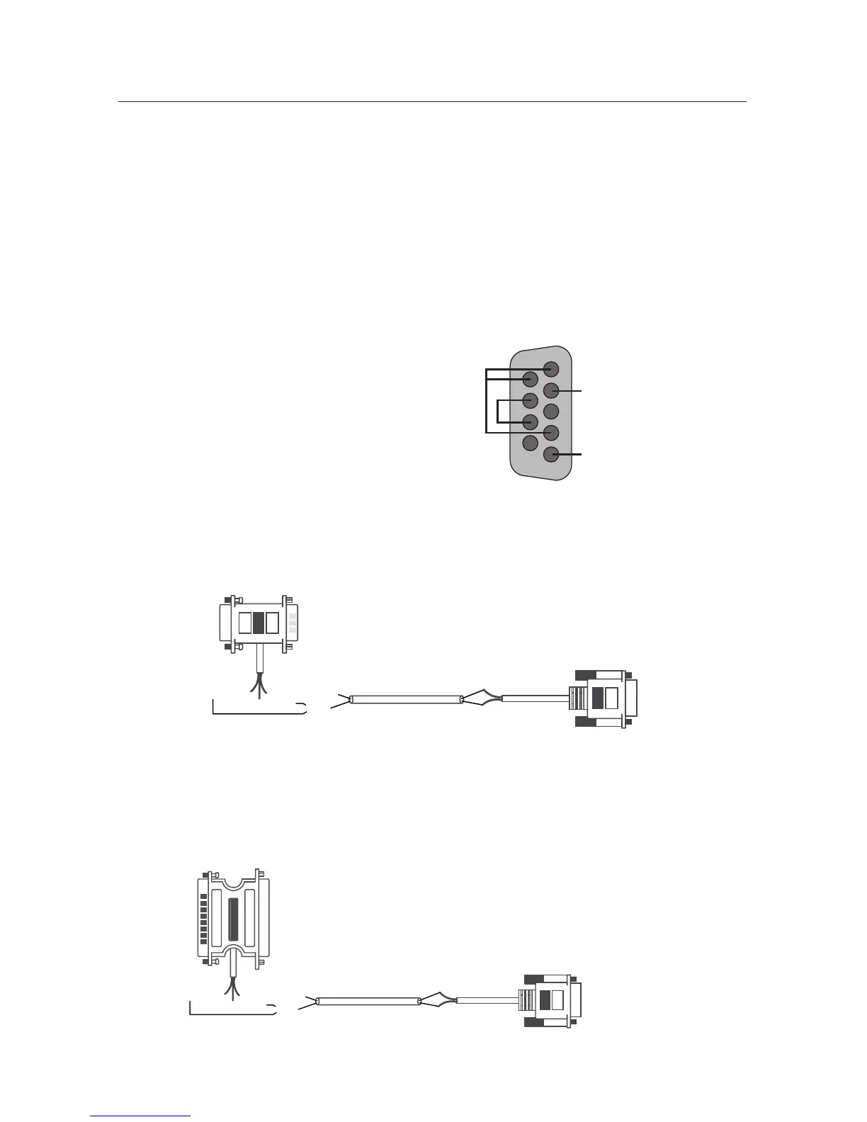
DVR Pigtail Internal Wiring
If you are utilizing the POS Interface feature, ensure that you have obtained the
correct interface connector from Image Vault for the approved device. Warning:
You can harm the DVR by connecting a data device that is not approved by
Image Vault and/or by using an improperly constructed cable. If you manu-
facture your own cable, tap the POS device as follows:
• Data (RX) at the POS printer tap goes to Pin 2 at the DVR.
• POS ground goes to Pin 5 at the DVR.
• At the DVR short Pins 7 and 8 together; short Pins 1, 4 and 6 together;
leave Pins 3 and 9 open.
• Wiring from the data source to journal printer depends on the device
manufacturer.
IV-9 POS Wiring to 9-Pin Serial Printer
This diagram illustrates the proper wiring of the IV-9 pigtail kit used to capture
data at serial printers with DB9 inputs.
DB9P
Pass-thru Connector
DB9F
DVR Connector
DVR PIGTAILHOME RUN WIREIV-9 POS PIGTAIL
Female Side
To Printer
Black (Pin 5)
18 AWG Twisted Pair
White (Pin 3)
OR*
Red (Pin 2)
Black (Pin 5)
Red (Pin 2)
Male Side
To Data Source
To DVR POS
PORT 1 or 2
IV-25 POS Wiring to 25-Pin Serial Printer
This diagram illustrates the proper wiring of the IV-25 pigtail kit used to capture
data at serial printers with DB25 inputs.
DB25P
Pass-thru Connector
DB9F
DVR Connector
DVR PIGTAILHOME RUN WIREIV-25 POS PIGTAIL
Male Side
To Printer
Black (Pin 5)
18 AWG Twisted Pair
White (Pin 3)
OR*
Red (Pin 2)
Black (Pin 5)
Red (Pin 2)
Female Side
To Data Source
To DVR POS
PORT 1 or 2