<< Back to Contents
Copyright © Innovative Technology Ltd 2018 Doc: NV9 Range User Manual
Version: 1.0
Page 22 of 63
4.4 Lock Mounting
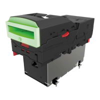
The NV9 range has an option for a 300-lockable cashbox. This is designed for a 300-
slide cashbox option.
ITL Part Number: PA00186
Webshop link: https://innovative-technology.com/shop/nv9-a-nv11-spares/nv9-300-
lockable-cashbox-detail
Details on the locking position can be found below.
4.4.1 Lock Fitting
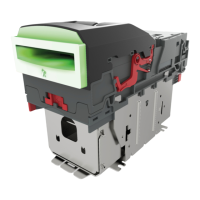
1. Screw Holes
The lockable door
attaches to the cashbox
housing via 3 x screw
holes, as shown.
These can be found on all
4 x sides of the cashbox.
Front Right; Front left
Back right; back let.
2. Locking Cam Slot
You’ll also see 4 x slots for
each position too. This is
where the lock slides into,
in order to lock the door
in place.
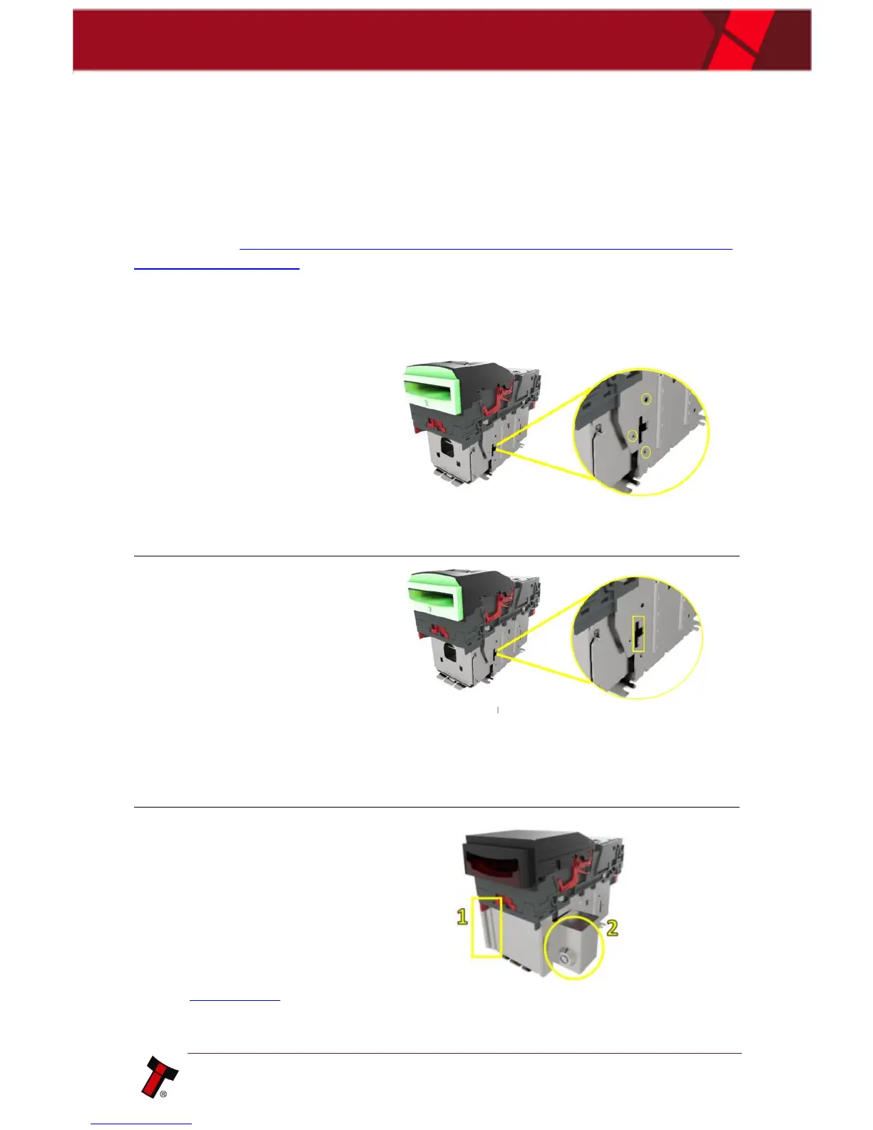
Please note: you want
to use the 3 x mounting
screw points, on the
opposite side of where
your lock will be.
For example:
if you want the lock to be Front
Right – you’d mount the door on the front left.
So that the door swings round and locks on the
side you specified.
3. Lock
Using front right as an
example, this specifies the
location of the lock (2).
In this case, the door is
mounted as seen (1).
Lock specification details
can be found below in
section 4.4.2.