Wiring
‑74‑
Servo drives in size C and size D (rated power: 1.0 kW to 1.5 kW): SV660PS7R6I and
SV660PS012I
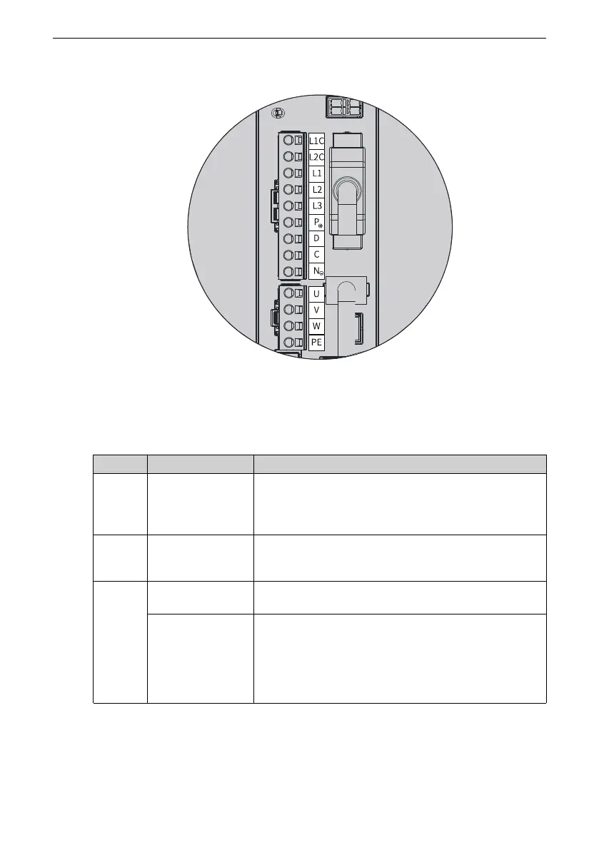
Figure 3‑13 Main circuit terminal pin layout of servo drives in size C (SV660PS7R6I) and size
D (SV660PS012I)
Table 3–3 Description of main circuit terminal pins of servo drives in size C (SV660PS7R6I)
and size D (SV660PS012I)
No. Name
Description
1
L1C, L2C
(control circuit
power input
terminals)
See the nameplate for the rated voltage class.
2
L1, L2, L3
(main circuit power
input terminals)
See the nameplate for the rated voltage class.
3
P⊕, NΘ
(DC bus terminals)
Used by the common DC bus for multiple servo drives.
P⊕, D, C
(terminals for
connecting
external
regenerative
resistor)
If an external regenerative resistor is needed, connect it
between terminals P⊕ and C. Servo drives in size C and
size D are equipped with the built‑in regenerative
resistor, with terminals P⊕ and D jumpered by default.

 Loading...


