Wiring
‑98‑
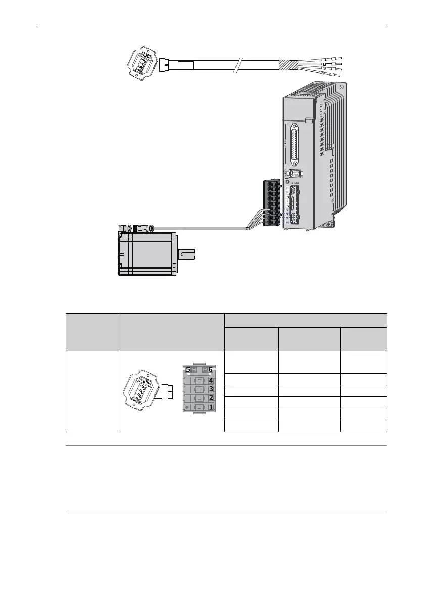
Figure 3‑27 Wiring between the servo drive and terminal‑type motor
Table 3–21 Description of the power cable connector (motor side)
Applicable
Motor Flange
Size
[1]
Outline Drawing of the
Connector
Terminal Pin Layout
Pin No.
Signal Name
Color
Terminal‑
type motor:
40 (Z series)
60 (Z series)
80 (Z series)
Black 6‑pin connector
1 PE
Yellow/
Green
2 W
Red
3 V
Black
4 U
White
5
Brake (polarity
insensitive)
Brown
6
Blue
Note
● [1] The flange size refers to the width of the mounting flange.
● Power cable colors are subject to the actual product. All cable colors mentioned in
this guide refer to Inovance cable colors.
● The wiring diagram for a lead wire‑type motor is shown in the following figure.

 Loading...


