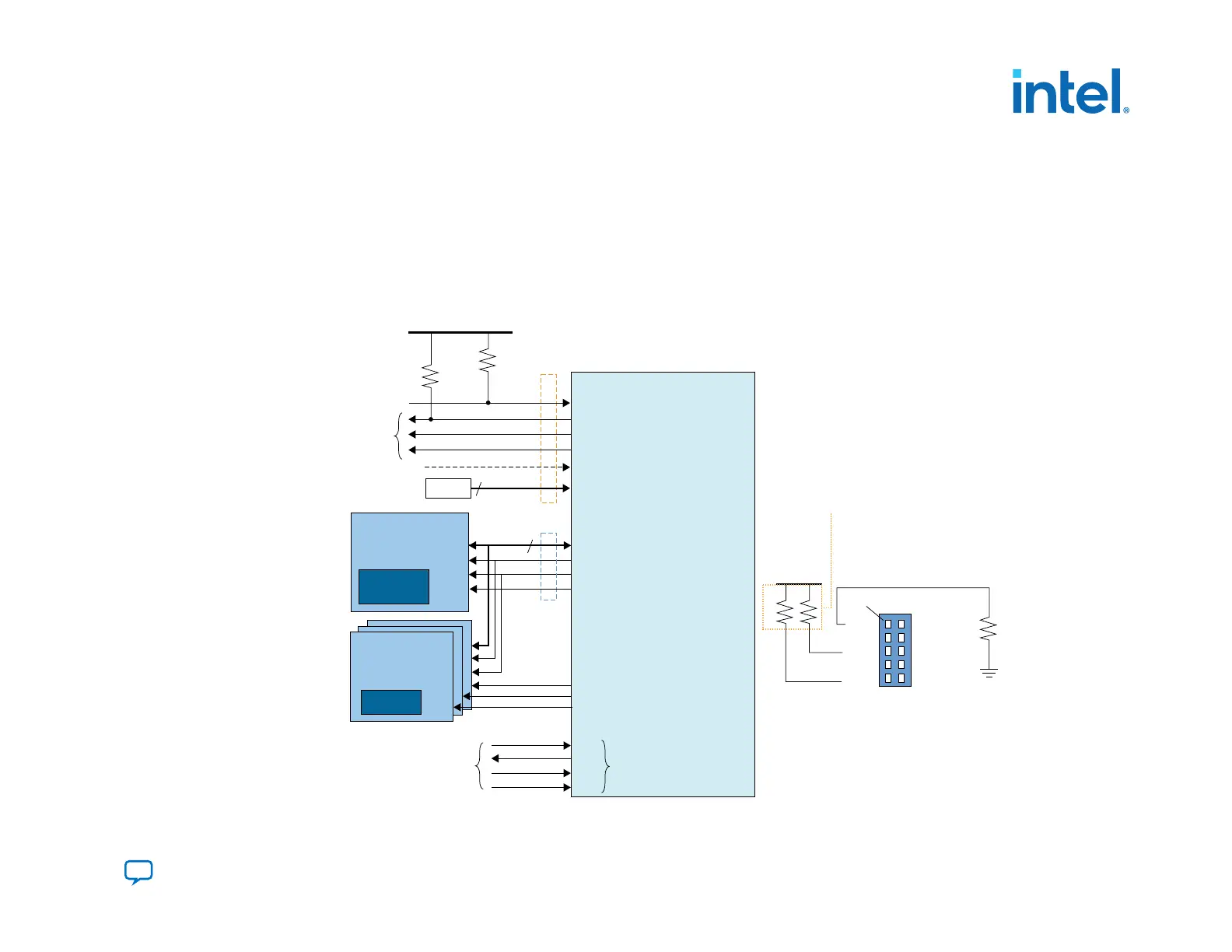
3.2.3. AS Using Multiple Serial Flash Devices
Intel Agilex devices support one AS x4 flash memory device for AS configuration and up to three AS x4 flash memories for
use with HPS data storage. The MSEL pins operate as MSEL only during POR state. After SDM samples the MSEL pins during
the boot ROM state for AS x4 mode, the SDM will repurpose the MSEL pins as chip select pins. You must to ensure appropriate
chip select pin connections to the configuration AS x4 flash memory and the HPS AS x4 flash memory. Each flash device has a
dedicated AS_nCSO pin but shares other pins.
Figure 39. Connections for AS Configuration with Multiple Serial Flash Devices
Pin 1
R
UP
R
DN
R
UP
TCK
TDO
TMS
OPEN
TDI
GND
VCCIO_SDM
OPEN
OPEN
GND
G
ND
V
CCIO_SDM
Intel FPGA
nCONFIG
nSTATUS
CONF_DONE
INIT_DONE
OSC_CLK_1
MSEL[2:0]
AS_DATA[3:0]
Config AS x4 Memory
AS_CLK
AS_nCS0[0]
AS_nCS0[1]
AS_nCS0[2]
AS_nCS0[3]
Download cable 10 pin male header (JTAG mode)
DATA[3:0]
DCLK
nCS
Configuration
Control Signals
Configuration
Data Signals
Optional
Monitoring
10kΩ
Optional
HPS Data Signals
MSEL
V
CCIO_SDM
3
4
To JTAG Header
or JTAG Chain
TCK
TDO
TDI
TMS
JTAG
Configuration
Pins
FPGA
Image (.rpd)
HPS AS x4 Memory
DATA[3:0]
DCLK
nCS
HPS Data
10kΩ
AS_nRST
nReset
nReset
Resistor values can vary between 1 kΩ to 10 kΩ.
Perform signal integrity analysis to select
the resistor value for your setup.
3. Intel Agilex Configuration Schemes
683673 | 2021.10.29
Send Feedback
Intel
®
Agilex
™
Configuration User Guide
107

 Loading...


