Skew delay includes the following elements:
• The delay due to the differences in board traces lengths on the PCB
• The capacitance loading of the flash device
The table below lists the maximum allowable skew delay depending on the AS_CLK frequency. Intel recommends that you to
perform IBIS simulations to ensure that the skew delay does not exceed the maximum delay specified in this table.
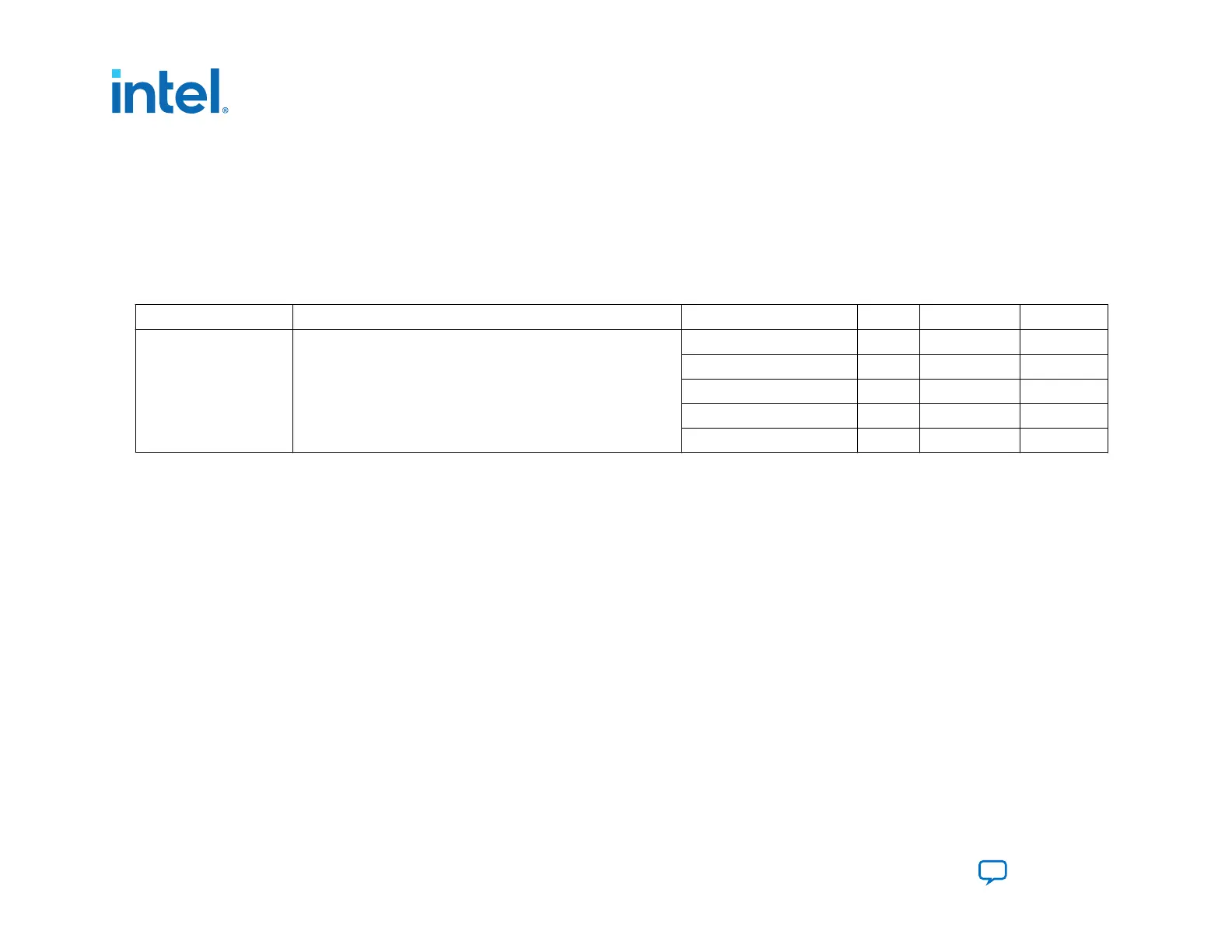
Table 35. Maximum Skew for AS Data Pins in Nanoseconds (ns)
Symbol Description Frequency Min Typical Max
T
ext_skew
Skew delay for AS_DATA for the AS_CLK frequency specified
166 MHz — — 3.6
125 MHz — — 4.0
115 MHz — — 4.2
100 MHz — — 5.0
<100 MHz — — 5.0
3.2.6. Programming Serial Flash Devices
You can program serial flash devices in-system using the Intel FPGA Download Cable II or Intel FPGA Ethernet Cable.
You have the following two in-system programming options:
• Active Serial
• JTAG
3.2.6.1. Programming Serial Flash Devices using the AS Interface
When you select AS programming the Intel Quartus Prime software or any supported third-party software programs the
configuration data directly into the serial flash device.
You must set MSEL to JTAG. When MSEL is set to JTAG, the SDM tristates the following AS pins: AS_CLK, AS_nRST,
AS_DATA0-AS_DATA3, and AS_nCSO0-AS_nCSO3. The Intel Quartus Prime Programmer programs the flash memory devices
via the AS header. If you are using the Generic Serial Flash Interface Intel FPGA IP to write the flash memory the flash device
must be connected to GPIO to access the flash device.
3. Intel Agilex Configuration Schemes
683673 | 2021.10.29
Intel
®
Agilex
™
Configuration User Guide
Send Feedback
110

 Loading...


