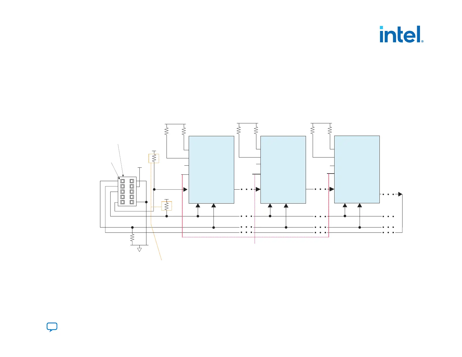
• One JTAG-compatible header connects to several devices in a JTAG chain. The drive capability of the download cable is the
only limit on the number of devices in the JTAG chain.
•
If you have four or more devices in a JTAG chain, buffer the TCK, TDI, and TMS pins with an on-board buffer. You can also
connect other Intel FPGA devices with JTAG support to the chain.
3.3.3.1. JTAG Multi-Device Configuration using Download Cable
Figure 53. Connection Setup for JTAG Multi Device Configuration using Download Cable
Pin 1
1 kΩ
10 kΩ
TMS TCK
TDI
TDO
nSTATUS
nCONFIG
MSEL[2:0]
CONF_DONE
TMS TCK
TDI
TDO
nSTATUS
nCONFIG
MSEL[2:0]
CONF_DONE
Intel FPGA Intel FPGA Intel FPGA
TMS TCK
TDI
TDO
nSTATUS
nCONFIG
MSEL[2:0]
CONF_DONE
Download cable
10-pin male header
(JTAG mode)
Resistor values can vary between 1 kΩ to 10 kΩ.
Perform signal integrity to select the resistor
value for your setup.
For JTAG configuration only:
Connect MSEL [2:0] of Intel FPGA devices to VCCIO_SDM through 4.7 kΩ external pull-up resistor.
For JTAG in conjunction with another configuration scheme:
Connect MSEL [2:0] of Intel FPGA devices based on the non-JTAG configuration scheme.
GND
V
CCIO_SDM
V
CCIO_SDM
V
CCIO_SDM
V
CCIO_SDM
10 kΩ
10 kΩ
V
CCIO_SDM
10 kΩ
10 kΩ
V
CCIO_SDM
10 kΩ
3. Intel Agilex Configuration Schemes
683673 | 2021.10.29
Send Feedback
Intel
®
Agilex
™
Configuration User Guide
131

 Loading...


