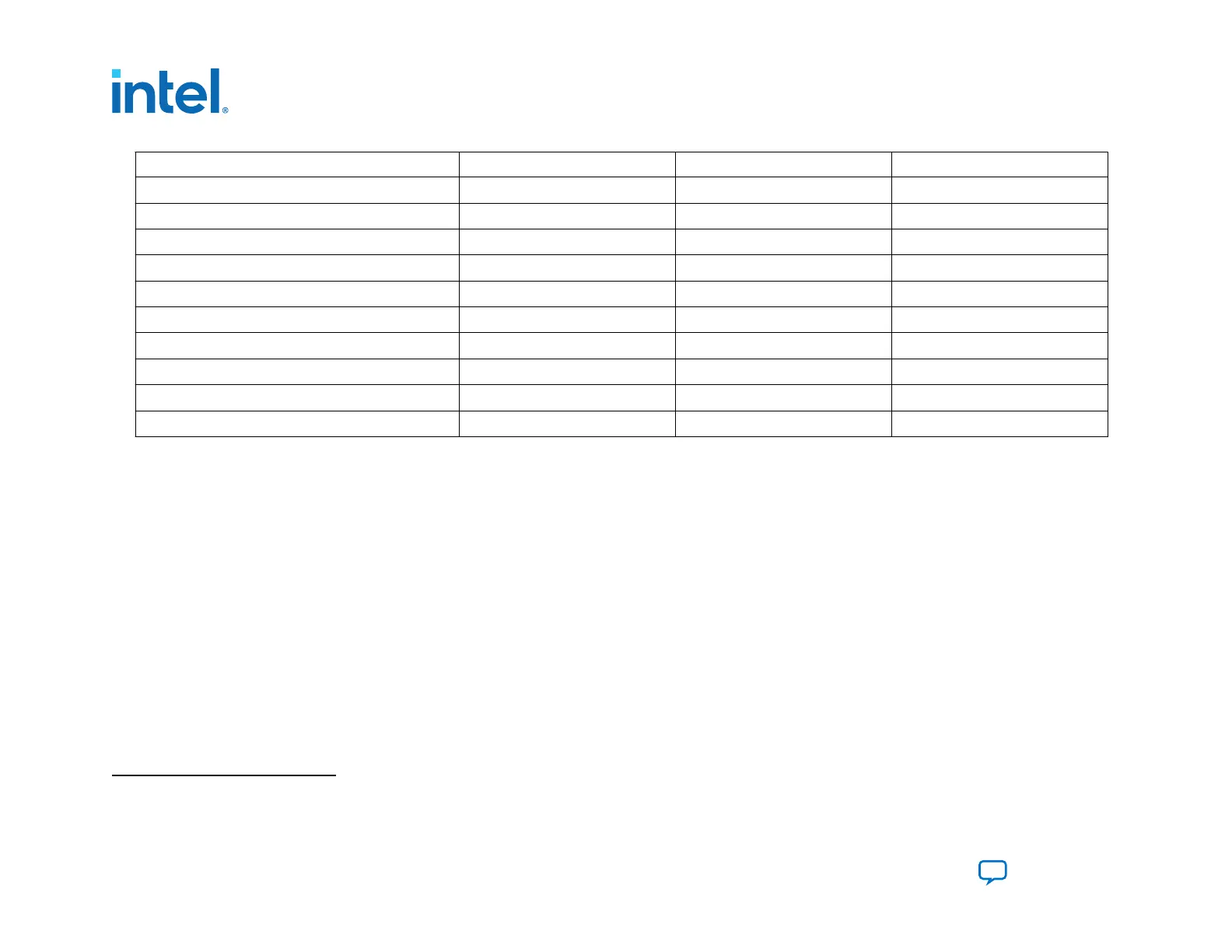
Signal Name Pin Type Direction Powered by
MSEL[2:0]
SDM I/O Input V
CCIO_SDM
CONF_DONE
(9)
SDM I/O Output V
CCIO_SDM
AVSTx8_READY
SDM I/O Output V
CCIO_SDM
AVST_READY
GPIO, Dual-Purpose Output V
CCIO
AVSTx8_DATA[7:0]
SDM I/O Input V
CCIO_SDM
AVSTx8_VALID
SDM I/O Input V
CCIO_SDM
AVSTx8_CLK
SDM I/O Input V
CCIO_SDM
AVST_DATA[31:0]
GPIO, Dual-Purpose Input V
CCIO
AVST_VALID
GPIO, Dual-Purpose Input V
CCIO
AVST_CLK
GPIO, Dual-Purpose Input V
CCIO
Refer to the Intel Agilex Data Sheet for configuration timing estimates.
The x16 and x32 modes use GPIO pins that only support the 1.2 V I/O standard. The SDM I/O pins require a 1.8 V power
supply. Consequently, you may need a voltage-level translation between the FPGA and external host because of some signals,
to accommodate both power requirements.
Attention: Access to the I/O pins located in bank 3A with pin index[91...95] is not allowed for the AVSTx16 or x32 configuration scheme.
You must leave these pins unconnected. For more information, refer to the device pin mapping files to identify the exact pin
location.
Note:
Although the INIT_DONE configuration signal is not required for configuration, Intel recommends that you use this signal. The
SDM drives the INIT_DONE signal high to indicate the device is fully in user mode. This signal is important when debugging
configuration.
Note: If you create custom logic instead of using the PFL II IP to drive configuration, refer to the Avalon Streaming Interfaces in the
Avalon Interface Specifications for protocol details.
(9)
CONF_DONE is required if you are using the Intel FPGA Parallel Flash Loader II IP as the configuration host.
3. Intel Agilex Configuration Schemes
683673 | 2021.10.29
Intel
®
Agilex
™
Configuration User Guide
Send Feedback
54

 Loading...


