Intel Desktop Board D815EEA2/D815EPEA2 Technical Product Specification
16
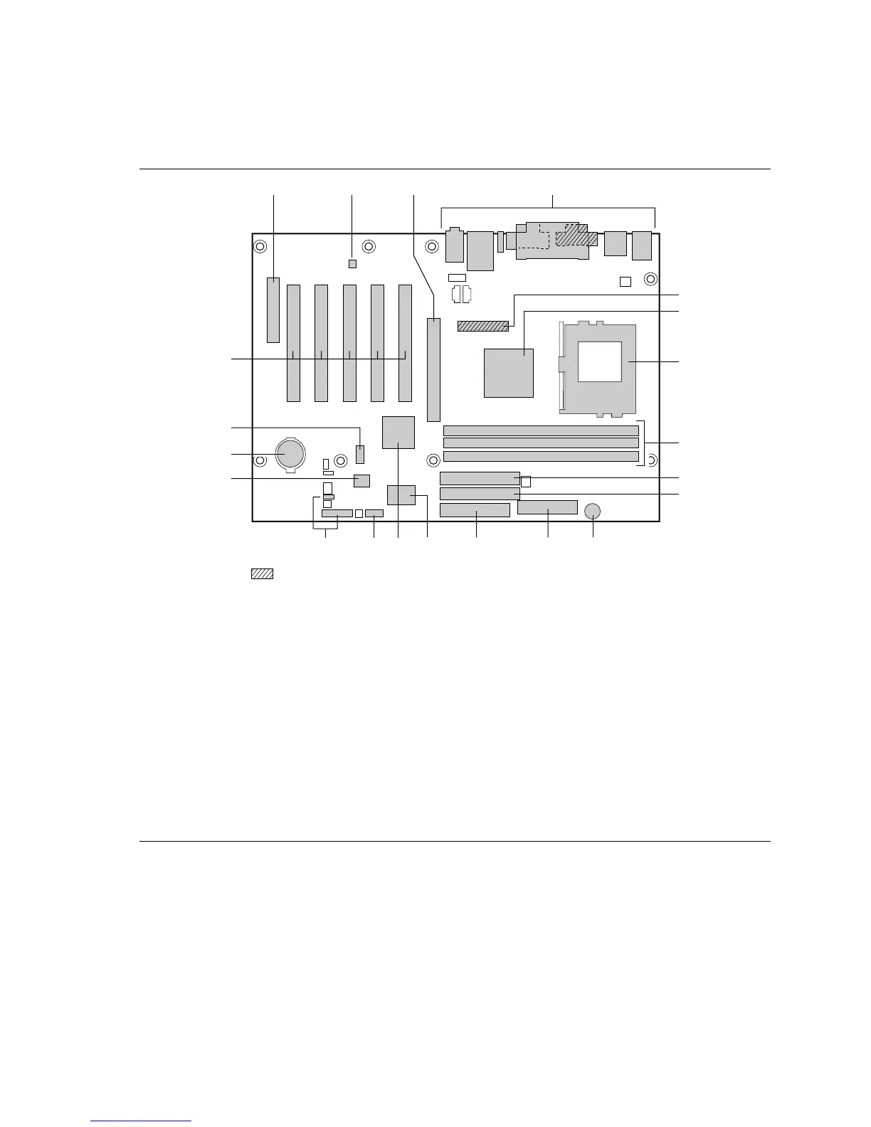
1.2.3 Board Layout
Figure 2 shows the location of the major components on the D815EEA2 and D815EPEA2 boards.
OM11461
D
A C
G
E
F
O
N
Q
P M KL
B
U
S
T
R
H
I
J
Present only on D815EEA2 boards
J Primary IDE connector A Communication and Networking Riser (CNR)
connector (optional)
K Speaker
B AD1885 audio codec L Power connector
C AGP universal connector M Diskette drive connector
D Back panel connectors N SMSC
LPC47M132 I/O Controller
E DVO connector (optional) O Intel
82801BA I/O Controller Hub (ICH2)
P Serial port B connector
Q Front panel connectors
R SST 49LF004A 4 Mbit Firmware Hub (FWH)
F
• Intel
82815 Graphics and Memory Controller
Hub (GMCH) (D815EEA2 boards)
• Intel
82815EP Memory Controller Hub (MCH)
(D815EPEA2 boards)
S Battery
G Processor socket T Front panel USB connector (optional)
H DIMM sockets U PCI bus add-in card connectors
I Secondary IDE connector
Figure 2. Board Components