Intel Desktop Board D815EEA2/D815EPEA2 Technical Product Specification
70
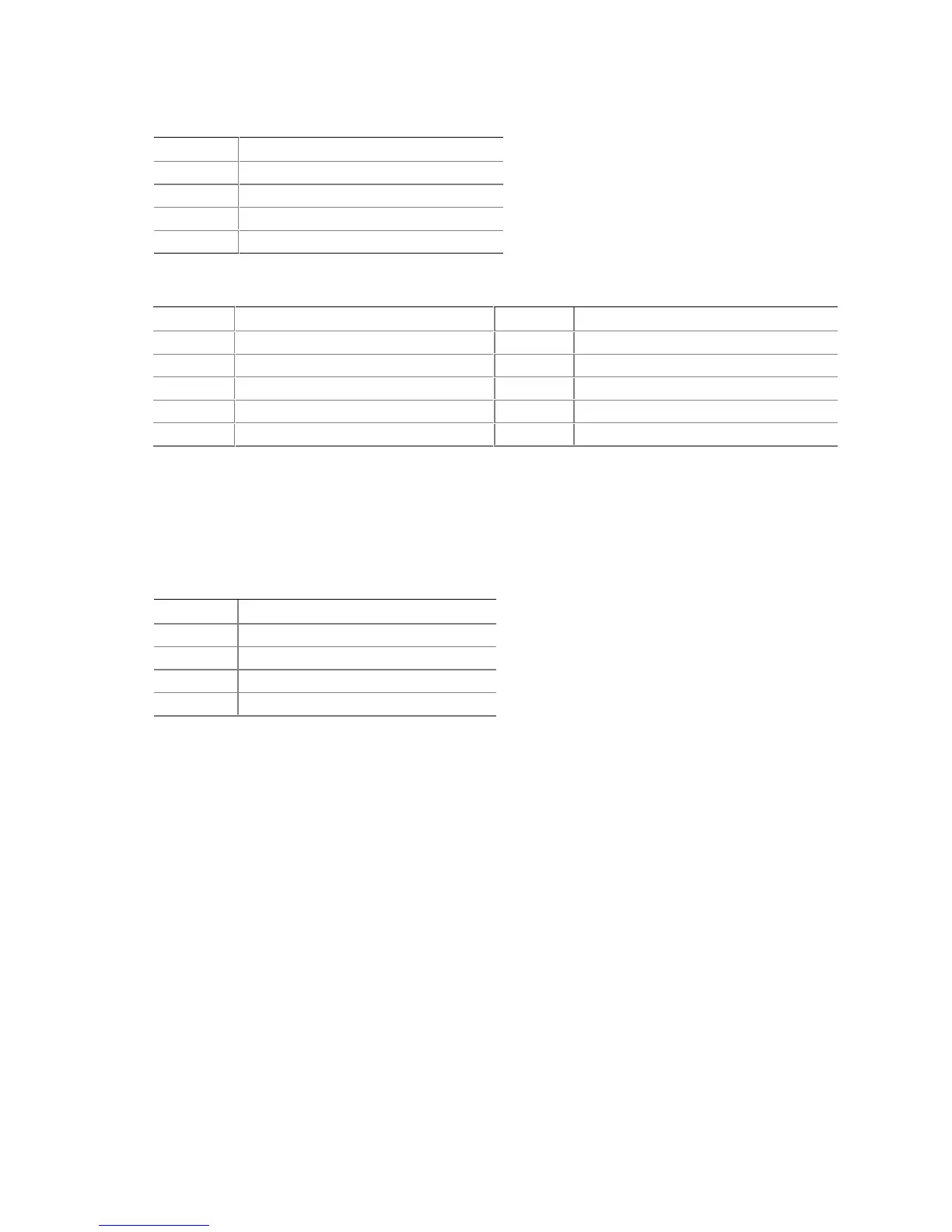
Table 29. Auxiliary Line In Connector (J6B4)
Pin Signal Name
1 Left auxiliary line in
2 Ground
3 Ground
4 Right auxiliary line in
Table 30. Front Panel Audio Connector (J6B2) (Optional)
Pin Signal Name Pin Signal Name
1 MICIN_FP 2 Ground
3 MIC_BIAS 4 AUD_ANALOG
5 AUD_FPOUT_R 6 AUD_RET_R
7 Reserved 8 (Pin removed)
9 AUD_FPOUT_L 10 AUD_RET_L
✏
NOTE
The front panel audio connector is alternately used as a jumper block for routing audio signals.
Refer to Section 2.9.1 on page 82 for more information.
Table 31. ATAPI CD-ROM Connector (J6B3)
Pin Signal Name
1 Left audio input from CD-ROM
2 CD audio differential ground
3 CD audio differential ground
4 Right audio input from CD-ROM