Product Description
47
1.13.3 Fan Control and Monitoring
The SMSC LPC47M132 I/O controller and the optional SMSC LPC47M142 I/O controller both
provide fan tachometer input for the processor fan (fan 1) and system fan (fan 2) and fan control
output for the system fan (fan 2) and the chassis fan (fan 3). Monitoring and control can be
implemented using third-party software.
For information about Refer to
The functions of the fan connectors Section 1.15.2.2, page 53
The location of the fan connectors Figure 14, page 69
The signal names of the fan connectors Section 2.8.2.2, page 69
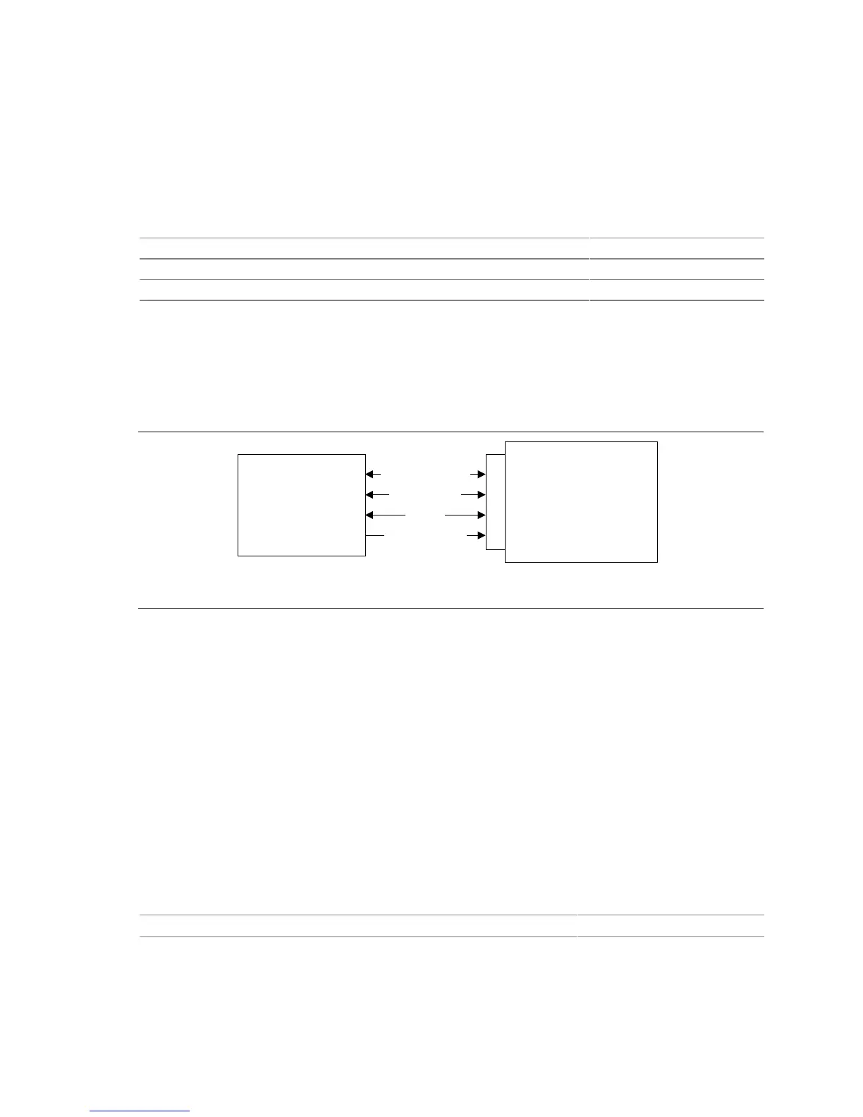
1.14 CNR Connector (Optional)
The CNR connector supports the audio, modem, USB, and LAN interfaces of the Intel 815E and
Intel 815EP chipsets. Figure 10 shows the signal interface between the riser and the ICH2.
Intel 82801BA
I/O Controller Hub
(ICH2)
Communication and
Networking Riser
(Up to two AC ’97 codecs
and one LAN device)
CNR Connector
AC ’97 Interfaces
LAN Interface
SMBus
OM11484
USB (Optional)
Figure 10. ICH2 and CNR Signal Interface
✏
NOTE
The USB interface from the ICH2 to the CNR is optional on this board.
The interfaces supported by the CNR connector include (but are not limited to) the following:
• AC ’97 interface: supports audio and/or modem functions on the CNR board.
• LAN interface: interface includes an eight-pin interface for use with Platform LAN Connect
(PLC) based devices.
• SMBus interface: provides Plug-and-Play functionality for the CNR board.
• USB interface (optional): provides a USB interface for the CNR board.
To learn more about the CNR, refer to the CNR specification.
For information about Refer to
Obtaining the CNR specification Table 4, page 20