Intel Desktop Board D815EEA2/D815EPEA2 Technical Product Specification
82
2.9 Jumper Blocks
CAUTION
Do not move any jumpers with the power on. Always turn off the power and unplug the power cord
from the computer before changing a jumper setting. Otherwise, the board could be damaged.
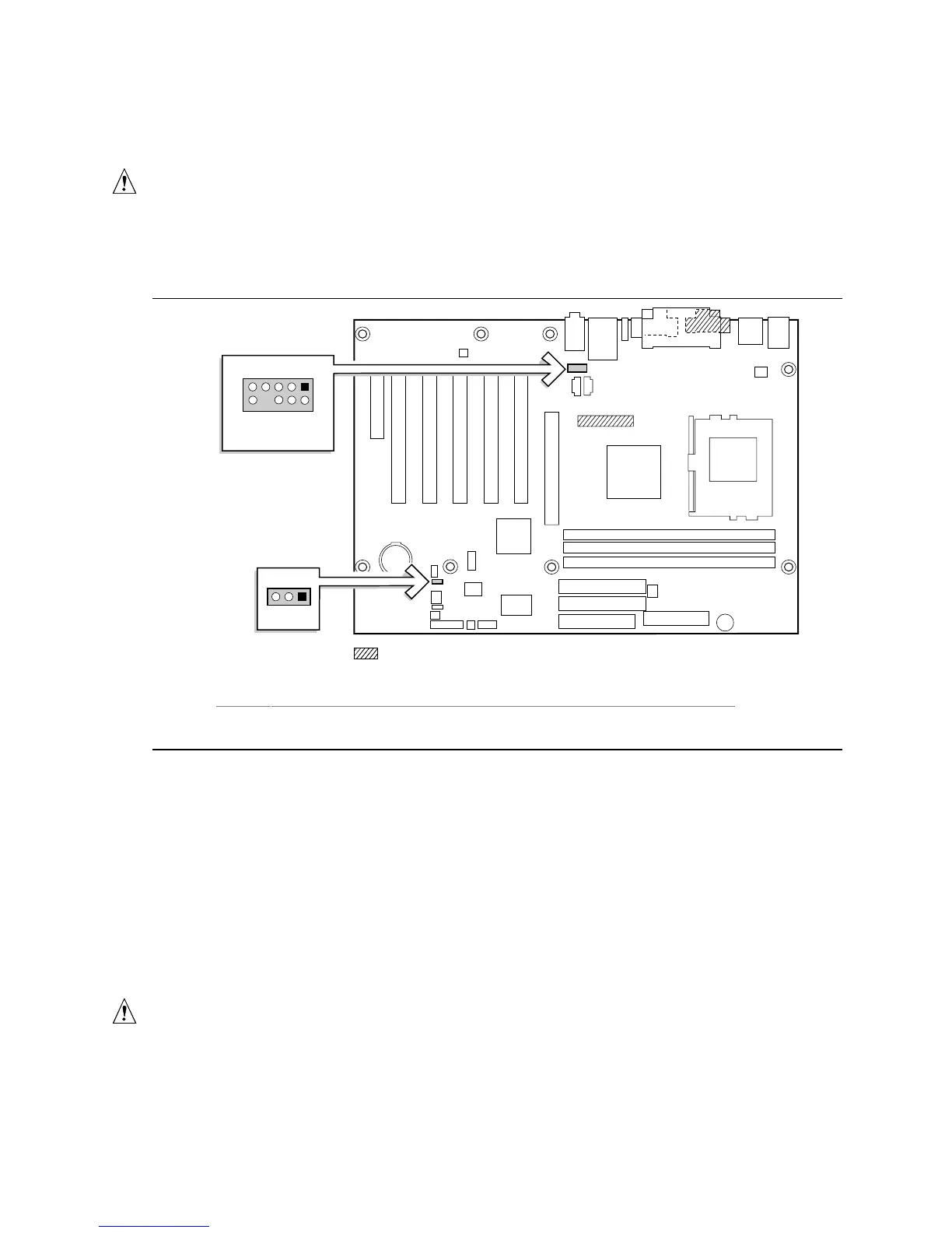
Figure 17 shows the locations of the jumper blocks on the D815EEA2 and D815EPEA2 boards.
OM11781
Present only on D815EEA2 boards
13
J9G2
13
J6B2
57
24610
9
A
B
Item Description Reference Designator
A Front panel audio connector / jumper block J6B2
B BIOS Setup configuration jumper block J9G2
Figure 17. Locations of the Jumper Blocks
2.9.1 Front Panel Audio Connector/Jumper Block
The connector at location J6B2 has two functions:
• With jumpers installed, the audio line out signals are routed to the back panel audio line out
connector.
• With jumpers removed, the connector provides audio line out and mic in signals for front panel
audio connectors.
Table 51 describes the two configurations of this connector/jumper block.
CAUTION
Do not place jumpers on this block in any configuration other than the one described in Table 51.
Other jumper configurations are not supported and could damage the board.