Technical Reference
69
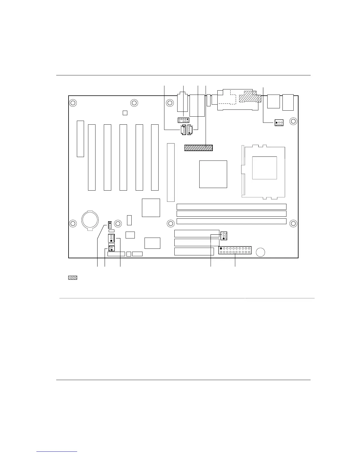
2.8.2.2 Audio, Video, Power, and Hardware Control Connectors
Figure 14 shows the location of the audio, video, power, and hardware control connectors on the
D815EEA2 and D815EPEA2 boards.
OM11464
A
B
D
1
4
4
10
9
2
1
J I FH
E
1
1
1
1
11
10
20
1
Present only on D815EEA2 boards
1
G
1
C
Item Description Color Reference Designator For more information see:
A Auxiliary line in, ATAPI style White J6B4 Table 29
B Front panel audio (optional) White J6B2 Table 30
C ATAPI CD-ROM Black J6B3 Table 31
D Digital video out (optional) N/A J5C1 Table 32
E Processor fan (fan 1) N/A J1B1 Table 33
F Power N/A J4H1 Table 34
G Chassis fan (fan 3) (optional) N/A J4G1 Table 35
H System fan (fan 2) N/A J9H1 Table 36
I Chassis intrusion (optional) N/A J9H3 Table 37
J Wake on LAN technology (optional) N/A J9G1 Table 38
Figure 14. Audio, Video, Power, and Hardware Control Connectors