Intel Desktop Board D815EEA2/D815EPEA2 Technical Product Specification
80
2.8.3.3 Front Panel Connector
This section describes the functions of the front panel connector. Table 48 lists the signal names of
the front panel connector.
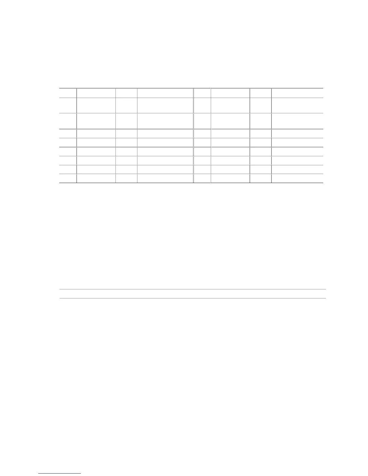
Table 48. Front Panel Connector (J9H3)
Pin Signal In/Out Description Pin Signal In/Out Description
1 HD_PWR Out Hard disk LED pull-
up (330 Ω) to +5 V
2 HDR_BLNK_
GRN
Out Front panel green
LED
3 HDA# Out Hard disk activity
LED
4 HDR_BLNK_
YEL
Out Front panel yellow
LED
5 GND Ground 6 FPBUT_IN In Power switch
7 FP_RESET# In Reset switch 8 GND Ground
9 +5 V Out Power 10 N/C Not connected
11 N/C Reserved 12 GND Ground
13 GND Ground 14 (pin removed) Not connected
15 N/C Reserved 16 +5 V Out Power
2.8.3.3.1 Reset Switch Connector
Pins 5 and 7 can be connected to a momentary SPST type switch that is normally open. When the
switch is closed, the D815EEA2 and D815EPEA2 boards reset and run the POST.
2.8.3.3.2 Hard Drive Activity LED Connector
Pins 1 and 3 can be connected to an LED to provide a visual indicator that data is being read from
or written to a hard drive. For the LED to function properly, an IDE drive must be connected to the
onboard IDE interface. The LED will also show activity for devices connected to the SCSI hard
drive activity LED connector.
For information about Refer to
The SCSI hard drive activity LED connector Section 2.8.3.2, page 79