Technical Reference
79
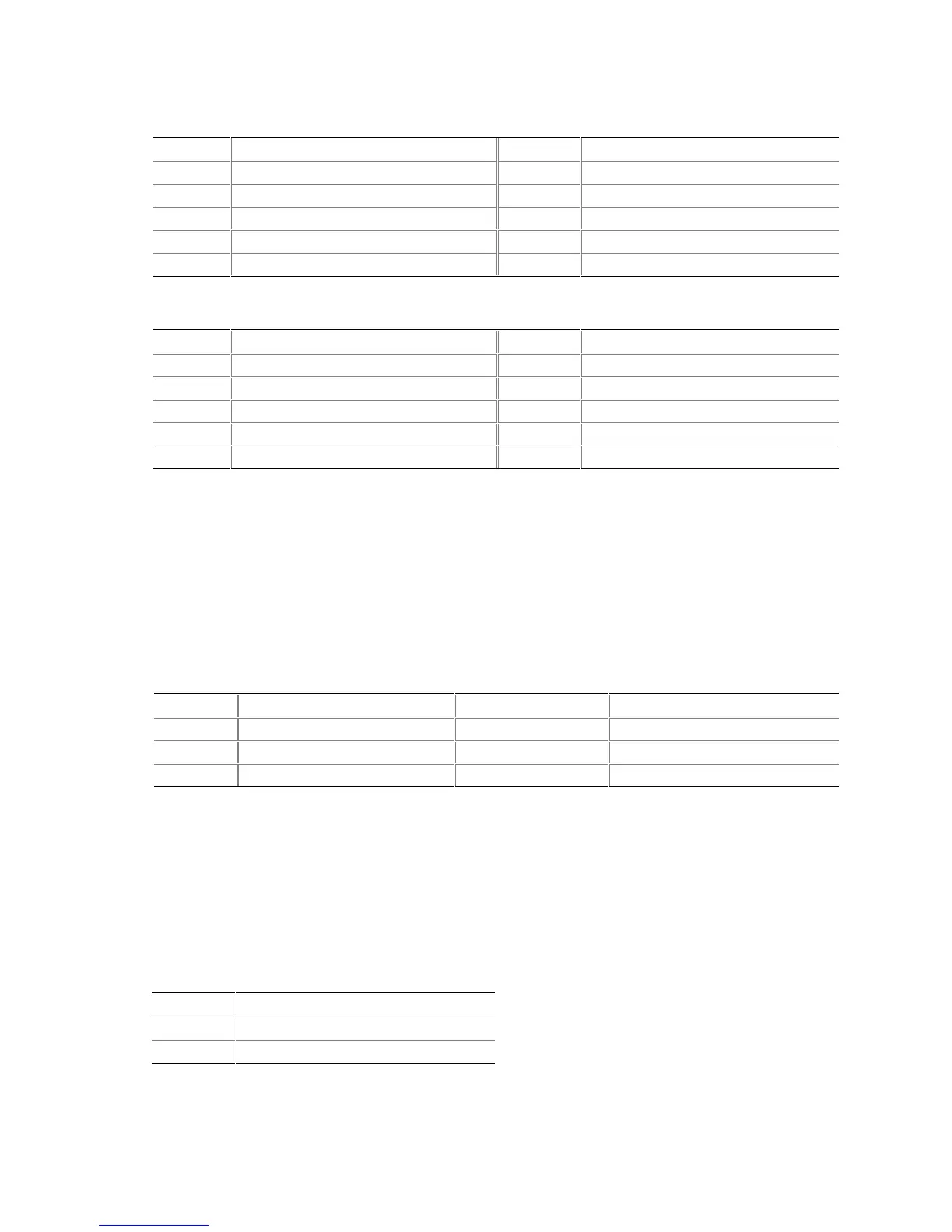
Table 44. Serial Port B Connector (J8H1)
Pin Signal Name Pin Signal Name
1 DCD2# 2 RXD2 (Receive Data)
3 TXD2 (Transmit Data) 4 DTR2#
5 Ground 6 DSR2#
7 RTS2# 8 CTS2#
9 RI2# 10 Key (no pin)
Table 45. Front Panel USB Connector (J8F1) (Optional)
Pin Signal Name Pin Signal Name
1 VREG_FP_USB_PWR 2 VREG_FP_USB_PWR
3 ICH_FP0# 4 ICH_FP1#
5 ICH_FP0 6 ICH_FP1
7 Ground 8 Ground
9 Key (no pin) 10 ICH_U_OC1_2#
✏
NOTE
A thermistor provides overcurrent protection for the front panel USB connector. The maximum
current through this connector is 1.5 A (total for both ports combined).
2.8.3.1 Auxiliary Front Panel Power LED Connector
This connector duplicates the signals on pins 2 and 4 of the front panel connector.
Table 46. Auxiliary Front Panel Power LED Connector (J9H2)
Pin Signal Name In/Out Description
1 HDR_BLNK_GRN Out Front panel green LED
2 Not connected
3 HDR_BLNK_YEL Out Front panel yellow LED
2.8.3.2 SCSI Hard Drive Activity LED Connector
The SCSI hard drive activity LED connector is a 1 x 2-pin connector that allows add-in SCSI host
bus adapter to use the same LED as the IDE controller. This connector can be connected to the
LED output of the add-in controller card. The LED will indicate when data is being read or written
using the add-in controller. Table 47 lists the signal names of the SCSI hard drive activity LED
connector.
Table 47. SCSI LED Connector (J8H2)
Pin Signal Name
1 SCSI activity
2 Not connected