Intel Desktop Board D815EEA2/D815EPEA2 Technical Product Specification
54
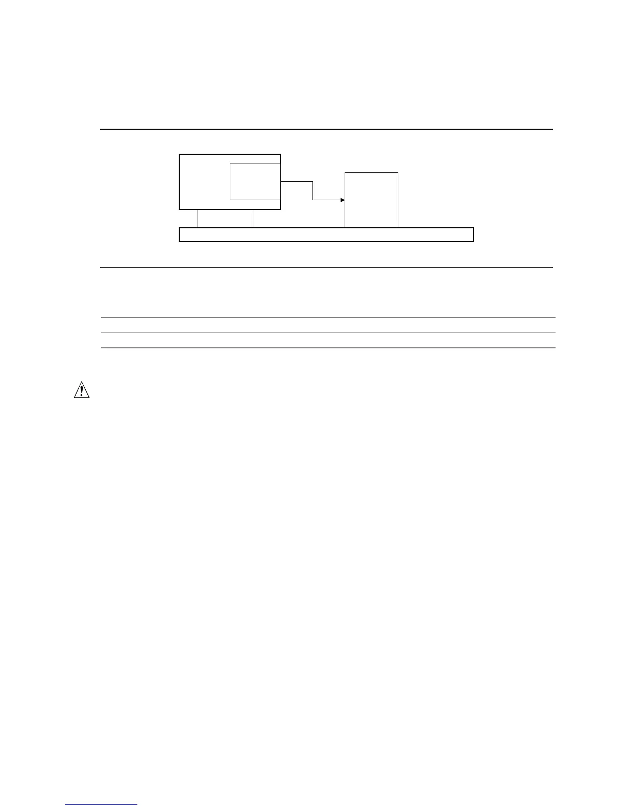
The Wake on LAN technology connector can be used with PCI bus network adapters that have a
remote wake up connector, as shown in Figure 11. Network adapters that are PCI 2.2 compliant
assert the wakeup signal through the PCI bus signal PME# (pin A19 on the PCI bus connectors).
Desktop Board
PCI Slot
Wake on
LAN
technology
connector
Network
Interface
Card
Remote
Wake up
connector
OM09129
Figure 11. Using the Wake on LAN Technology Connector
For information about Refer to
The location of the optional Wake on LAN technology connector Figure 14, page 69
The signal names of the optional Wake on LAN technology connector Table 38, page 72
1.15.2.4 Instantly Available Technology
CAUTION
For Instantly Available technology, the 5 V standby line for the power supply must be capable of
providing adequate +5 V standby current. Failure to provide adequate standby current when
implementing Instantly Available technology can damage the power supply. Refer to Section 2.11.3
on page 94 for additional information.
Instantly Available technology enables the D815EEA2 and D815EPEA2 boards to enter the
ACPI S3 (suspend-to-RAM) sleep-state. While in the S3 sleep-state, the computer will appear to
be off (the power supply is off, the fans are off, and the front panel LED is amber if dual-color, or
off if single-color.) When signaled by a wake-up device or event, the system quickly returns to its
last known wake state.
The D815EEA2 and D815EPEA2 boards support the PCI Bus Power Management Interface
Specification. Add-in boards that also support this specification can participate in power
management and can be used to wake the computer.
The use of Instantly Available technology requires operating system support and PCI 2.2 compliant
add-in cards and drivers.
The standby power indicator LED (at location CR6E1) shows that power is still present at the
DIMM and PCI bus connectors, even when the computer appears to be off. Figure 12 shows the
location of the standby power indicator LED on the D815EEA2 and D815EPEA2 boards.