Intel® Server Board S2600WF Product Family Technical Product Specification
120
Appendix B. POST Code Diagnostic LED Decoder
As an aid in troubleshooting a system hang that occurs during a system POST process, the server board
includes a bank of eight POST code diagnostic LEDs on the back edge of the server board.
During the system boot process, Memory Reference Code (MRC) and system BIOS execute a number of
memory initialization and platform configuration processes, each of which is assigned a hex POST code
number.
As each routine is started, the given POST code number is displayed to the POST code diagnostic LEDs on
the back edge of the server board.
During a POST system hang, the displayed POST code can be used to identify the last POST routine that was
run prior to the error occurring, helping to isolate the possible cause of the hang condition.
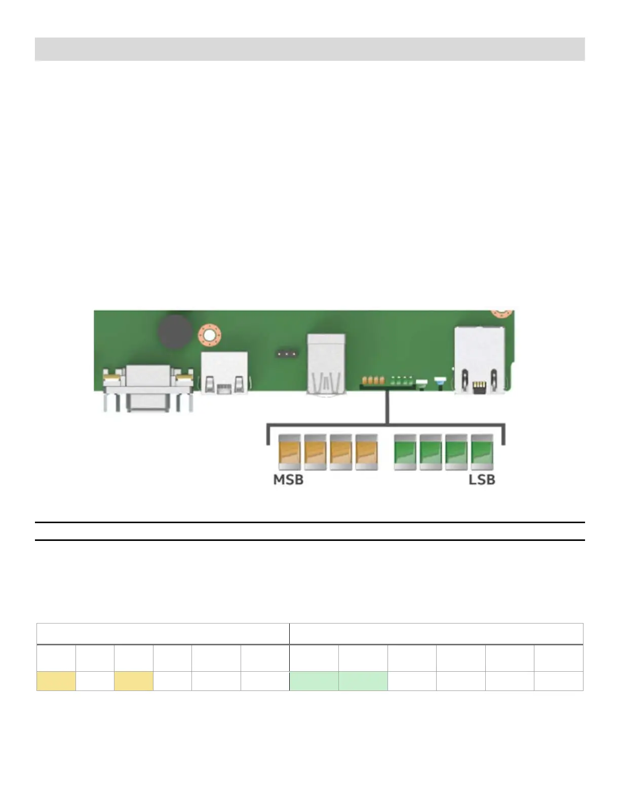
Each POST code is represented by eight LEDs, four green and four amber. The POST codes are divided into
two nibbles, an upper nibble and a lower nibble. The upper nibble bits are represented by amber diagnostic
LEDs and the lower nibble bits are represented by green diagnostics. If the bit is set in the upper and lower
nibbles, the corresponding LED is lit. If the bit is clear, the corresponding LED is off. For each set of nibble
bits, LED 0 represents the least significant bit (LSB) and LED 3 represents the most significant bit (MSB).
Figure 75. Onboard POST diagnostic LED location and definition
Note: Diagnostic LEDs are best read and decoded when viewing the LEDs from the back of the system.
In the following example, the BIOS sends a value of AC to the diagnostic LED decoder. The LEDs are decoded
as shown in Table 52, where the upper nibble bits represented by the amber LEDs equal 1010
b
or A
h
and the
lower nibble bits represented by the green LEDs equal 1100
b
or C
h
. The two are concatenated as AC
h
.
Table 52. POST progress code LED example
Upper Nibble Lower Nibble
LED 2 LED 1
LED 2 LED 1
ON off ON off 1010 A ON ON off off 1100 C
Upper Nibble (amber)
(Read first)
Lower Nibble (green)
(Read second)
8h 1h
2h 4h 8h
1h 2h
4h