Intel® Server Board S2600WF Product Family Technical Product Specification
83
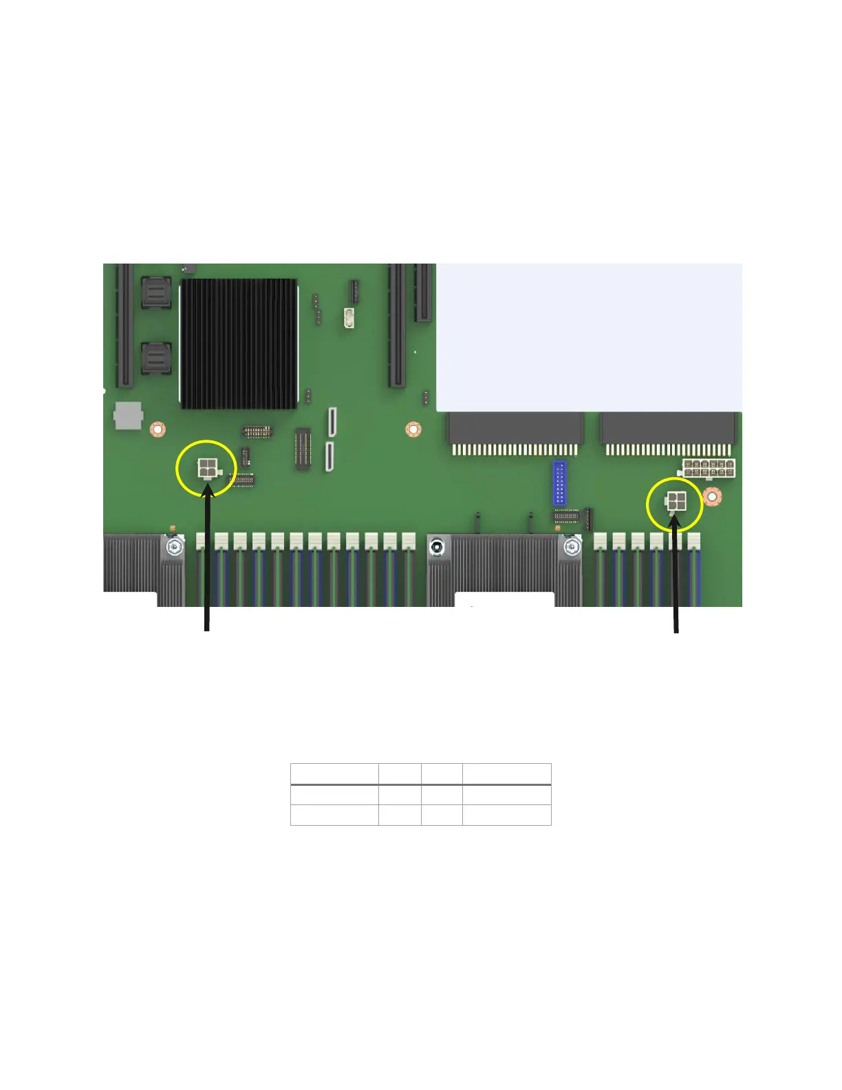
7.1.3 Riser Card Supplemental 12-V Power Connectors
The server board includes two white 2x2-pin power connectors labeled “OPT_12V_PWR” that provide
supplemental 12 V power-out to high power PCIe x16 add-in cards (video, GPGPU, Intel® Xeon Phi™
coprocessor) that have power requirements that exceed the 75 W maximum power supplied by the riser card
slot. These connectors are identified in Figure 59. A cable from these connectors may be routed to a power-
in connector on the given add-in card. Maximum power draw for each connector is 225 W, but is also limited
by available power provided by the power supply and the total power draw of the given system
configuration. A power budget for the complete system should be performed to determine how much
supplemental power is available to support any high-power add-in cards.
Figure 59. Riser slot auxiliary power connectors
Table 34 provides the pinout values for the 12-V power connectors.
Table 34. Riser slot auxiliary power connector pinout ("OPT_12V_PWR”)
Intel makes available a 12-V supplemental power cable that can support both 6- and 8-pin 12-V AUX power
connectors found on high power add-in cards. The power cable (as shown in Figure 60) is available as a
separate orderable accessory kit (iPC – AXXGPGPUCABLE).
OPT_12V_PWR OPT_12V_PWR