Intel® Server Board S2600WF Product Family Technical Product Specification
86
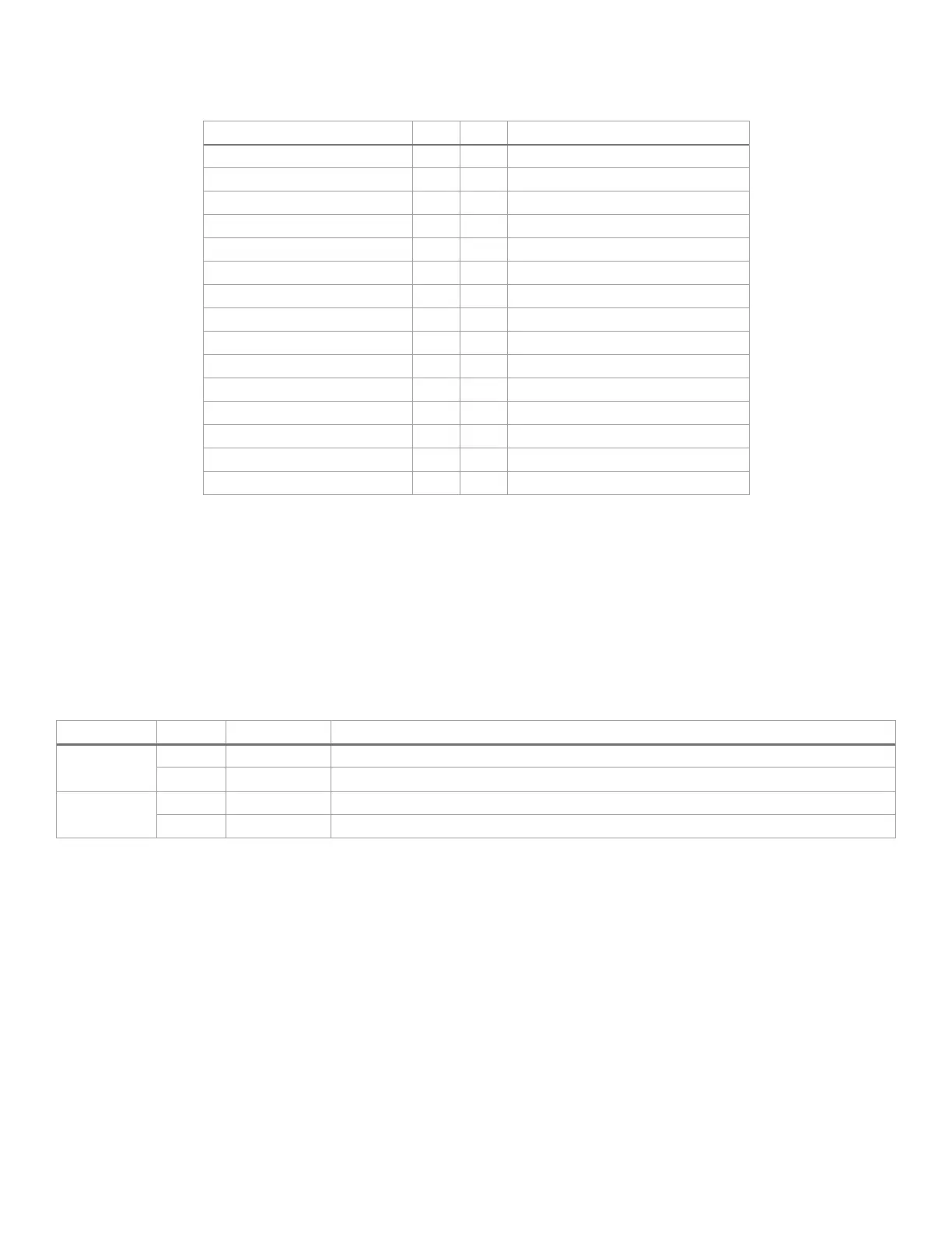
The pinout for both connector types, shown in Table 37, is identical.
Table 37. 30-pin front panel connector pinouts
LED _NIC_LINK0_LNKUP_FP_N
SMB_SENSOR_3V3STBY_DATA_R0
7.2.1 Front Panel LED and Control Button Features Overview
7.2.1.1 Power/Sleep Button and LED Support
Pressing the power button toggles the system power on and off. This button also functions as a sleep button
if enabled by an ACPI-compliant operating system. Pressing this button sends a signal to the integrated BMC,
which powers on or powers off the system. The power LED is a single color and is capable of supporting
different indicator states as defined in Table 38.
Table 38. Power/sleep LED functional states
Non-ACPI
System power is off and the BIOS has not initialized the chipset.
ACPI
Mechanical is off and the operating system has not saved any context to the hard disk.
System and the operating system are up and running.
7.2.1.2 System ID Button and LED Support
Pressing the system ID button toggles both the ID LED on the front panel and the blue ID LED on the back
edge of the server board. The system ID LED is used to identify the system for maintenance when installed in
a rack of similar server systems. The system ID LED can also be toggled on and off remotely using the IPMI
“Chassis Identify” command which causes the LED to blink for 15 seconds.
7.2.1.3 System Reset Button Support
When pressed, this button reboots and re-initializes the system.
7.2.1.4 NMI Button Support
When the NMI button is pressed, it puts the server in a halt state and causes the BMC to issue a non-
maskable interrupt (NMI) for generating diagnostic traces and core dumps from the operating system. Once
an NMI has been generated by the BMC, the BMC does not generate another NMI until the system has been
reset or powered down.