EasyManua.ls Logo

Intel S2600WF - Hot Swap Backplane Power Connector; Figure 58. Hot Swap Backplane Power Connector; Table 33. Hot Swap Backplane Power Connector Pinout (HSBP PWR)

Intel S2600WF
140 pages
To Next Page IconTo Next Page
To Previous Page IconTo Previous Page
Loading...
Intel® Server Board S2600WF Product Family Technical Product Specification
82
Signal Name
Pin #
Pin#
Signal Name
P12V
B17
A17
P12V
P12V
B18
A18
P12V
P3V3_AUX: PU_PS2FRU_A0
B19
A19
SMB_PMBUS_DATA_R
P3V3_AUX: PD_PS2_FRU_A1
B20
A20
SMB_PMBUS_CLK_R
P12V_STBY
B21
A21
FM_PS_EN_PSU_N
FM_PS_CR1
B22
A22
IRQ_SML1_PMBUS_ALERTR3_N
P12V_SHARE
B23
A23
ISENSE_P12V_SENSE_RTN
TP_2_B24
B24
A24
ISENSE_P12V_SENSE
FM_PS_COMPATIBILITY_BUS
B25
A25
PWRGD_PS_PWROK
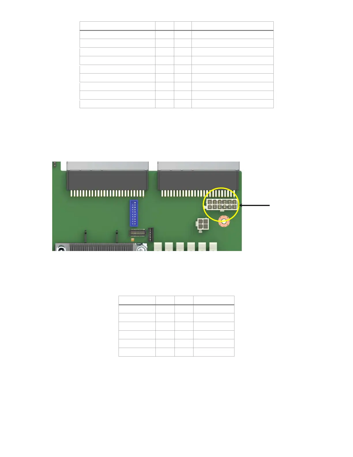
7.1.2 Hot Swap Backplane Power Connector
The server board includes one white 2x6-pin power connector that when cabled provides power for hot
swap backplanes, as shown in Figure 58. On the server board, this connector is labeled as “HSBP PWR”.
Figure 58. Hot swap backplane power connector
Table 33. Hot swap backplane power connector pinout (“HSBP PWR”)
Signal Name
Pin #
Pin #
Signal Name
GND
1
7
P12V_240VA3
GND
2
8
P12V_240VA3
GND
3
9
P12V_240VA2
GND
4
10
P12V_240VA2
GND
5
11
P12V_240VA1
GND
6
12
P12V_240VA1
Hot swap
backplane
connector

Table of Contents

Related product manuals