Intel® Server Board S2600WF Product Family Technical Product Specification
73
6.4.2 RJ45 Network Interface Connectors (Intel® Server Board S2600WFT only)
The Intel Server Board S2600WFT provides two RJ45 networking ports, “NIC #1” and “NIC #2”, in addition to
the RJ45 dedicated management port. The board includes the following onboard Intel® Ethernet Controller:
• Intel® Ethernet Controller X557-AT2 10 GbE
Refer to the respective product data sheet for a complete list of supported Intel Ethernet Controller features.
6.5 Serial Port Support
The server board has support for two serial ports: Serial-A and Serial-B.
Serial A is an external RJ45 type connector located on the back edge of the server board as shown in Figure
46. The pin orientation is shown in Figure 48 and the pinout is given in Table 25.
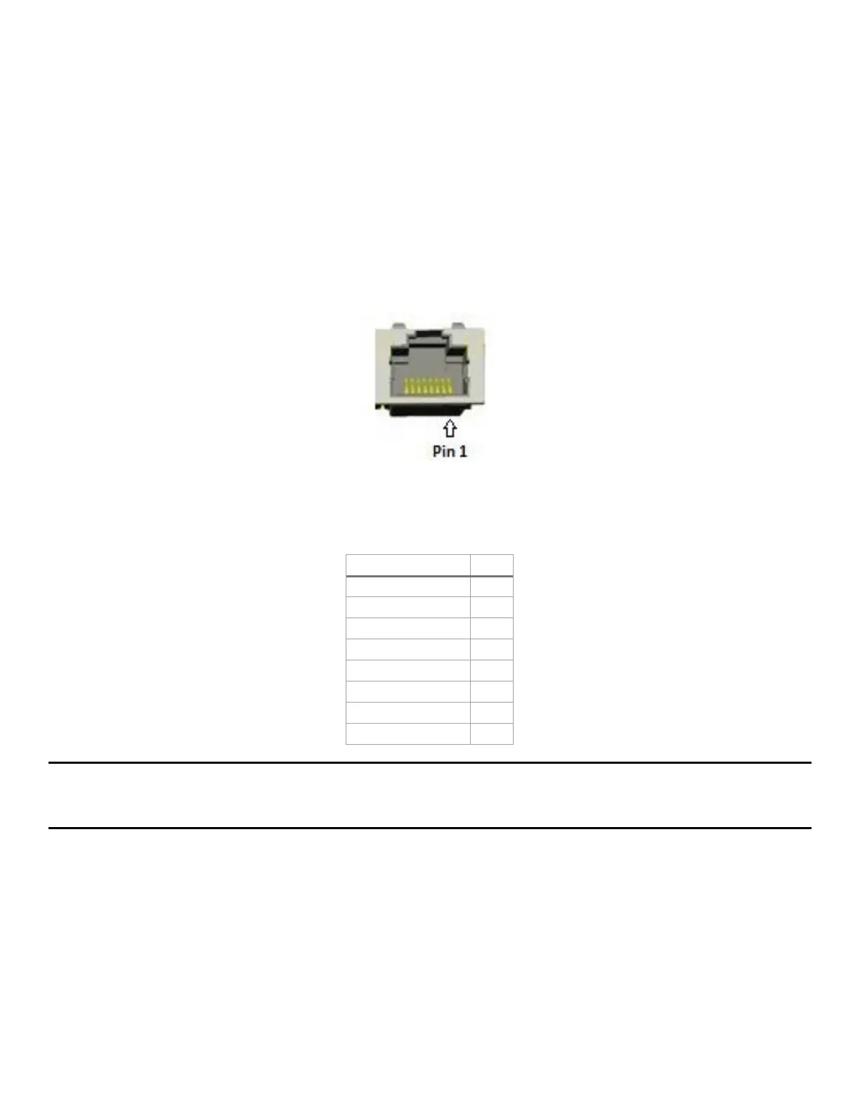
Figure 48. RJ45 Serial-A pin orientation
Table 25.Serial-A connector pinout
Note: Pin 7 of the RJ45 Serial-A connector is configurable to support either a DSR (default) signal or a DCD
signal. Pin 7 signals are changed by moving the jumper on the jumper block labeled labeled “J4A2“ from
pins 1–2 (default) to pins 2–3 as shown in
Figure 49.