Intel® Server Board S2600WF Product Family Technical Product Specification
72
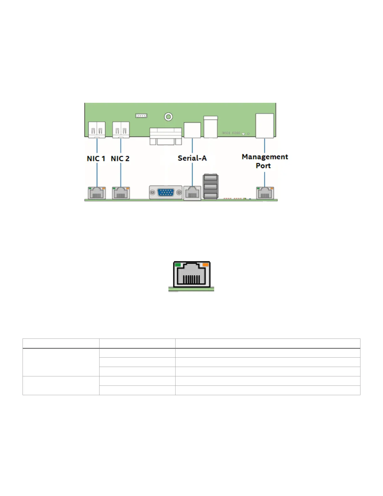
6.4 Rear External RJ45 Connector Overview
The back edge of the server board includes several RJ45 connectors providing support for the following
onboard features:
• Dedicated server management port
• Network interface connectors (S2600WFT only)
• Serial-A port (see Section 6.5)
Figure 46. Rear external RJ45 connectors
RJ45 connectors used for the dedicated management port and network interface connectors include two
LEDs. The LED on the left side of the connector is the link/activity LED and indicates network connection
when on, and transmit/receive activity when blinking. The LED on the right side of the connector indicates
link speed. Table 24 provides a full definition for the LED states.
Figure 47. RJ45 connector LEDs
Table 24. External RJ45 NIC port LED definition
Link/activity (left)
Transmit/receive activity
Transmit/receive (right)
6.4.1 RJ45 Dedicated Management Port
The server board includes a dedicated 1 GbE RJ45 management port. The management port is active with or
without the Intel® Remote Management Module 4 Lite Intel® RMM4 Lite) key installed. See Chapter 8 for
additional information about onboard server management support.