Intel® Server Board S2600WF Product Family Technical Product Specification
74
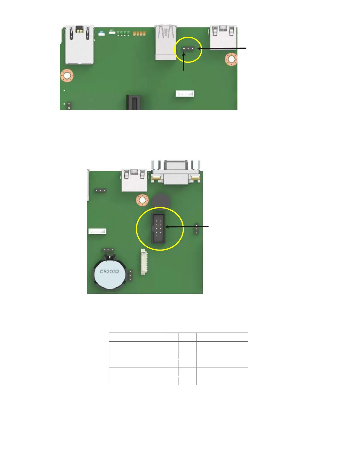
Figure 49. J4A2 Jumper block for Serial-A pin 7 configuration
Serial B is provided through an internal DH-10 header labeled “Serial_B” on the server board. The connector
location is shown in Figure 50 and the pinout is given in Table 26.
Figure 50. Serial-B connector (internal)
Table 26. Serial-B connector pinout
Serial-A
Pin 7 Config
Jumper
DSR: Pins 1-2
DCD: Pins 2-3
Pin 1
Serial-B Port
DH-10 Connector